Performance Levels (PL) Guide: ISO 13849-1 Machine Safety Explained
- Share
- publisher
- Vicky
- Issue Time
- Oct 25,2025
Summary
Learn how Performance Levels (PL) work under ISO 13849-1, how PLr is determined, and how to select safety components to achieve compliant, reliable machine protection.
Performance Levels (PL), defined in ISO 13849-1, are fundamental for designing safe and compliant machinery. Whether you are a machine builder or an equipment end-user, understanding PL helps ensure your safety functions work reliably—even under fault conditions.
To explore typical safety components used in PL-compliant systems, you may visit the DADISICK product overview page.
What Is a Performance Level (PL)?
Performance Level (PL) is a measure defined in the ISO 13849-1 standard. It indicates the ability of a machine's safety control system to perform its safety functions under foreseeable conditions.
In simple terms, PL quantifies how well a safety system can reduce risk — the higher the PL, the lower the probability that a dangerous failure will occur.
PL is categorised into five levels: PLa, PLb, PLc, PLd, and PLe.
· PLa–b: Basic Risk (Small automated equipment, simple switches)
· PLc: Medium Risk (Assembly equipment, packaging machines)
· PLd: High Risk (Robot units, punch presses)
· PLe: Extremely High Risk (Die-casting machines, shearing equipment, dangerous moving parts)
How to Determine the Required Performance Level (PLr)
Determining the Required Performance Level (PLr) is a fundamental step in ensuring functional safety and reducing machine-related risks to an acceptable level. The process, as defined by ISO 13849-1, should be conducted early in the machine design phase, when safety functions are being specified, and risk mitigation strategies are developed.
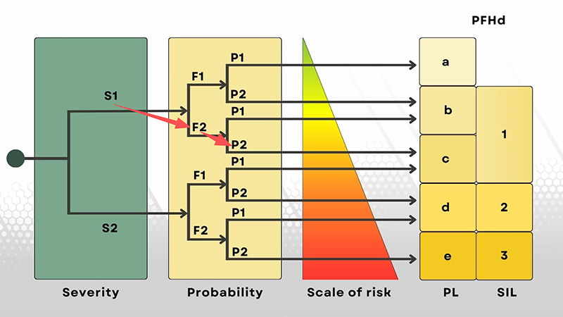
To identify the required PLr, engineers evaluate three key parameters using the standard risk graph:
· Severity of Injury (S): Determines how serious the potential harm could be. Minor or reversible injuries correspond to S1, while severe or irreversible injuries (including fatal accidents) correspond to S2.
· Frequency and Duration of Exposure (F): Refers to how often and how long an operator is exposed to a hazard. Occasional access is classified as F1, whereas frequent or constant exposure is F2.
· Possibility of Avoiding the Hazard (P): Evaluates whether the operator can reasonably avoid or limit harm once the hazard occurs. If avoidance is feasible, it is rated P1; if avoidance is nearly impossible, it is P2.
By combining these three parameters, the required Performance Level can be determined. For instance, a scenario involving minor injury potential (S1), frequent exposure (F2), and low avoidance possibility (P2) would lead to a Required Performance Level of PLr = C. In this case, the safety-related control system must meet PL C or higher (PL C–PL E) to ensure adequate protection. This systematic approach ensures that each safety function is designed with the appropriate reliability, aligning both with regulatory compliance and the operational safety goals of the machine.
How the Achieved PL Is Determined: Key Technical Indicators
Once PLr is identified, the next step is evaluating whether the designed safety function can actually meet that target.
ISO 13849-1 defines four essential technical indicators:
· Category (System Architecture)
Describes redundancy, fault tolerance, and behaviour during failure.
Higher categories (2, 3, 4) provide more robust protection.
· MTTF<sub>d</sub> — Mean Time to Dangerous Failure
Indicates how reliable the internal components are over time.
Longer MTTFd = more stable and dependable safety system.
· DC — Diagnostic Coverage
Measures how effectively the system detects internal faults.
Higher DC = higher achievable PL.
· CCF — Common Cause Failure Resistance
Ensures redundant channels won't fail simultaneously due to the same external influence (vibration, wiring, EMC interference, etc.).
PLr tells you what level of safety is required. These four indicators determine whether your design can reach that level. A machine is compliant only when PL ≥ PLr.
Practical Implications: Why PL Matters for Real-World Machinery
Performance Levels are not just technical classifications — they represent the measurable reliability of a machine's safety system. Establishing the correct PL ensures that safety-related components consistently perform their intended protective functions, even in the event of a fault or system stress.
A properly defined and validated PL brings several key advantages:
· Enhanced Safety Assurance: The system maintains a predictable and dependable safety response, minimizing the risk of injury or equipment damage.
· Regulatory Compliance: Meeting the appropriate PL fulfills international safety requirements, supporting conformity with ISO 13849-1 and global market standards.
· Operational Efficiency: Well-designed safety architectures reduce unnecessary interruptions, enabling continuous, safe, and efficient production.
· Long-Term Reliability: Verified PL levels help ensure the system's safety performance remains stable over its entire lifecycle.
In essence, Performance Levels bridge the gap between functional safety and industrial productivity. They provide engineers with a quantifiable benchmark for system integrity and give organizations the confidence that their automation processes meet the highest safety expectations.
Why High-Quality Safety Components Are Key — and How DADISICK Helps
Meeting a target PL is not just about design: it requires components that truly live up to reliability, diagnostic, and redundancy requirements. This is where DADISICK becomes valuable.
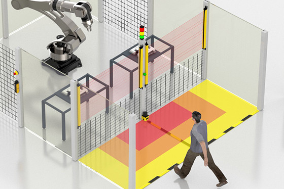
· DADISICK offers industrial-grade safety light curtains, interlock switches, safety relays, and other safety sensors — suitable for building safety-related control systems across a wide PL range.
· These components are designed for durability, stable performance, and integration into safety architectures — crucial when trying to achieve PL d or PL e.
· By selecting such components from the start, machine builders and users reduce uncertainty, make risk assessments more reliable, and simplify system validation against ISO 13849-1.
Therefore, for any application requiring robust safety — from robotic cells, presses, conveyors, to automated assembly lines — combining PL-based design with proven components offers the most reliable path to compliance and safety.
Conclusion: PL + Quality Components = Safer, Compliant Machinery
Performance Levels under ISO 13849-1 provide a robust and standardized method for assessing machine safety requirements based on actual risk. But without reliable, well-engineered safety components, even the best design may fail to deliver safety in practice.
By pairing PL-based design methodology with high-quality safety sensors and control components (such as those provided by DADISICK), machine builders and end-users can achieve safer, more reliable, and regulation-compliant machinery — protecting both workers and businesses.
If you plan to build or upgrade machinery with high safety demands, consider DADISICK's safety solutions as a foundation for achieving PL-compliant safety systems.
Recommended Related Safety Sensors

Beam spacing:40mm
Number of optical axes:20
Protection height:760mm
Safety sensors for machines output (OSSD):2 PNP
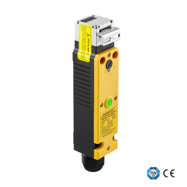
• 2 sets of gold-plated silver alloy contacts
• PA66 flame-retardant housing
• 6 contact combinations
• Locking force 1300 N
• Indicator light + emergency release
• Compatible with 11 types of operating keys
• Compact design saves space

Detection range: 5000 mm, 15000 mm
Material: Nickel-copper alloy
Connection type: 3pin/4pin with 2M cable

Installation type: Non-shielded
Detection range: 8mm, 16mm
Case material: Nickel-plated brass
Connection type: M12 Connector
Output method: NC/NO