Safety Relay DK-Ter-A Series with automatic and manual reset configurations
- Model
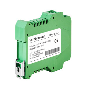
- DK-Ter-AN or DK-Ter-AP
Item specifics
- Power supply
- 24 V DC
- Relay safety output
- 3NO + 1NC
- Maximum switching capacity
- 12 A (Distributed on all safety output contacts)
- Transistor signal output
- <500 mA 24 V DC
- Contact resistance
- <100 mΩ
- Size
- 117 × 100 × 22.5 mm
- Class of pollution
- 4 TYPE
- Certificate
- ISO, CE, UL ,FCC, TUV
Review
Description
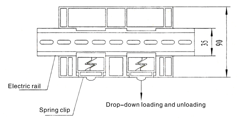
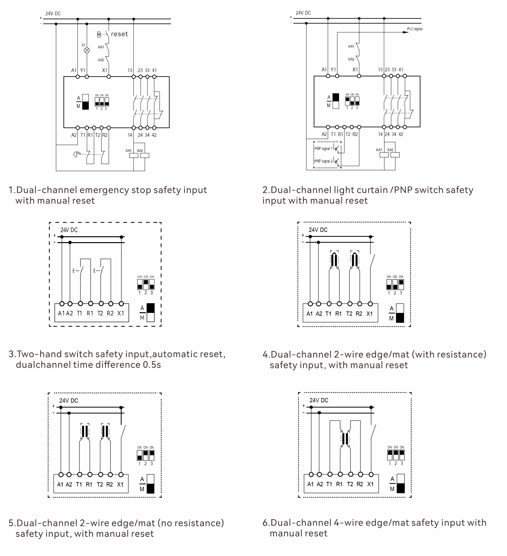
DADISICK Safety Relay DK-Ter-A Series is suitable for monitoring various signals in industrial sites with high safety requirements. The compact design of our Safety Relays reduces installation space, making them suitable for a wide range of industrial applications. They feature a width of just 22.5mm and come with screw or spring terminals for flexible installation options. The relays support PLC signal output and have I/O LED indicators for easy status monitoring. Additionally, they offer automatic/manual reset configurations and multi-function configuration dip switches, allowing for quick system setup and adaptation to different safety requirements.
|
Safety Relay Product model
|
|||
|
Safety relay series
|
DK-Ter-A
|
||
Output method | NPN | PNP | |
Product model | DK-Ter-AN | DK-Ter-AP | |
|
Output
|
|||||||
|
Power supply
|
24 V DC
|
||||||
|
Tolerance of voltage
|
+10% / -20%
|
||||||
|
Power dissipation
|
2.9 W
|
||||||
|
Output
|
3NO + 1NC
|
||||||
|
Transistor signal output
|
<500 mA 24V DC
|
||||||
|
Relay contact capacity
|
|||
|
AC-1
|
6 A / 250 V AC / 1500 VA
|
||
|
AC-15
|
4 A / 240 V AC
|
||
|
DG-1
|
6 A / 24 V DC / 150 W
|
||
|
DG-13
|
4 A / 24 V DC
|
||
Maximum switching capacity | 12 A (Distributed on all safety output contacts) | ||
Contact resistance | <100 mΩ | ||
Minimum load | 10 mA / 5V | ||
Material of contact | AgSnO2 + 0.2µmAu | ||
|
General parameter
|
|||
|
Output fuse (external)
|
5 A gL/gG
|
||
|
Release response time
|
<30 ms (From input to output)
|
||
|
Check the resistance at the end of the input component(Touch edge/carpet)
|
1 kΩ ~ 10 kΩ
|
||
|
Electrical life
|
80,000 times
|
||
Cass of pollution | 4 TYPE | ||
Operating temperature | -25℃ ~ 85℃ | ||
Operating humidity | 35% - 85% (No ice or condensation) | ||
Impulse withstand voltage | 2.5 kV | ||
Level of protection | Enclosure IP30, terminal IP20, recommended for installation in cabinet or enclosure IP54 | ||
Storage temperature | -40℃ ~ 105℃ | ||
Shell material | Flame retardant PA66 | ||
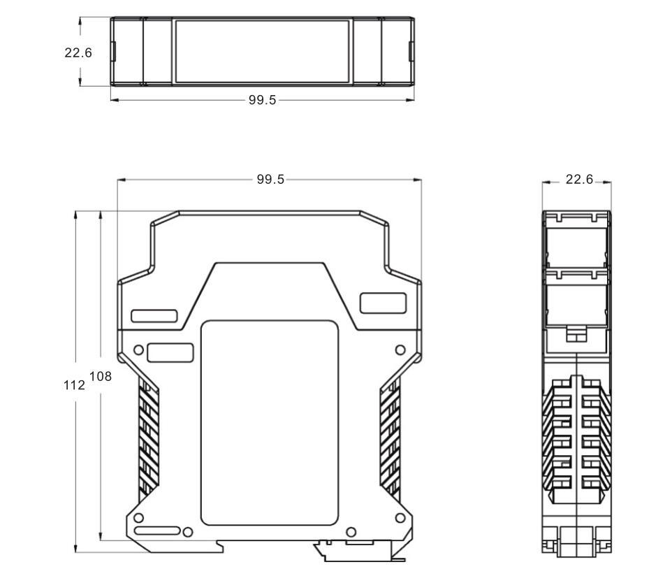
Size | 117 × 100 × 22.5 mm | ||