


GFL-G85PM | Laser Distance Measurement Sensor | DADISICK
- Model
- GFL-G Series | GFL-G85PM
Item specifics
- Response time:
- Up to 1.0ms
- Repetitive accuracy:
- Up to 2µm
- Detection distance:
- 85mm
- Detection range (f. s.):
- ±20mm
- Linear accuracy:
- ±0.1%f.8. (f.s.=40mm)
- Resolution ratio:
- 10um (In fast mode 15μm)
- Output:
- Analog/PNP
Review
Description
|
Laser Distance Measurement Sensor Measuring range specification
|
||||||
Model | Analog quantity | GFL-G30N(P)M | GFL-G50N(P)M | GFL-G85N(P)M | GFL-G120N(P)M | GFL-G250N(P)M |
RS485 communication | GFL-G30N(P)-485 | GFL-G50N(P)-485 | GFL-G85N(P)-485 | GFL-G120N(P)-485 | GFL-G250N(P)-485 | |
Detection distance |
30mm | 50mm | 85mm | 120mm | 250mm |
|
Detection Range (F.S.) | ±4mm | ±10mm | ±20mm | ±60mm | ±150mm |
|
illuminant | Red semiconductor laser | |||||
Wavelength: 655nm Maximum power: lmv | ||||||
Laser type | IEC/JIS | CLASS2 | ||||
FDA | CLASS II | |||||
Spot size *1 | Close range | 0.15x0.15mm | 0.6x1.2mm | 0.9x1.5mm | 1.2x1.8mm | 1.5x2.5mm |
Central position | 0.1x0.1mm | 0.5x1.0mm | 0.75x1.25mm | 1.0x1.5mm | 1.75x3.5mm | |
Long distance | 0.15x0.15mm | 0.4x0.9mm | 0.6x1.0mm | 0.5x0.8mm | 2.0x4.5mm | |
Linear accuracy | ±0.1%F.S. (F.S.=8mm) | ±0.1%F.S. (F.S.=20mm) | ±0.1%F.S. (F.S.=40mm) | ±0.1%F.S. (F.S.=120mm) | ±0.1%F.S. (F.S.=300mm) | |
Resolution | 2μm (4μm in fast mode) | 5μm (8μm in fast mode) | 10μm (15μm in fast mode) | 30μm (45μm in fast mode) | 75μm (150μm in fast mode) | |
Response time | High speed | max. 2ms | max. 2.5ms | |||
Standard | max. 11.5ms | max. 15.5ms | ||||
High precision | max. 36.5ms | max. 48.5ms | ||||
|
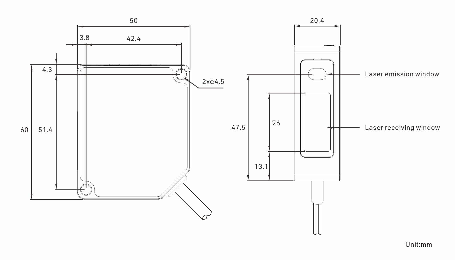
Mechanical parameters
|
||
|
Sampling period
|
550μs (250mm model: 750μs) |
|
|
Temperature drift characteristic
|
±0.08%F.S./℃ |
|
|
Pilot lamp
|
ON: Indicators OUT 1 and OUT 2 (yellow) are on |
|
|
MF input (Multi-function input
|
In the menu external input select: Zero, Teach, Stop laser. |
|
PN model: Grey MF wire connected to the negative terminal of the power supply (0V) is more than 20ms and disconnected for triggering once. PNP model: The grey MF wire is connected to the positive electrode of the power supply (24V) for more than 20ms and disconnected for triggering once. | ||
Protection circuit | Reverse connection protection, overcurrent protection | |
Protection class | IP64 | |
Use ambient temperature/humidity | 10+45℃(no icing)/35~85RH(no frost) | |
Storage ambient temperature/humidity | -20~60℃(no icing)/35~95RH(no frost) | |
Ambient illumination | Sunlight: less than 10000Lx Incandescent lamp: less than 3000Lx | |
Vibration resistance | 10-55Hz double amplitude 1.5mm XYZ for 2 hours in all directions | |
Impact resistance | About 50G(500m/s)X, Y, Z three times in each direction | |
Internal circuit stability time | Approx. 1.5s | |
Preheating time | max.15 minutes | |
Material | Case: Aluminum lens :PMMA | |
Cable type weight | 65g(without cable) | |
Plug-in type weight | 90g | |
DIMENSION
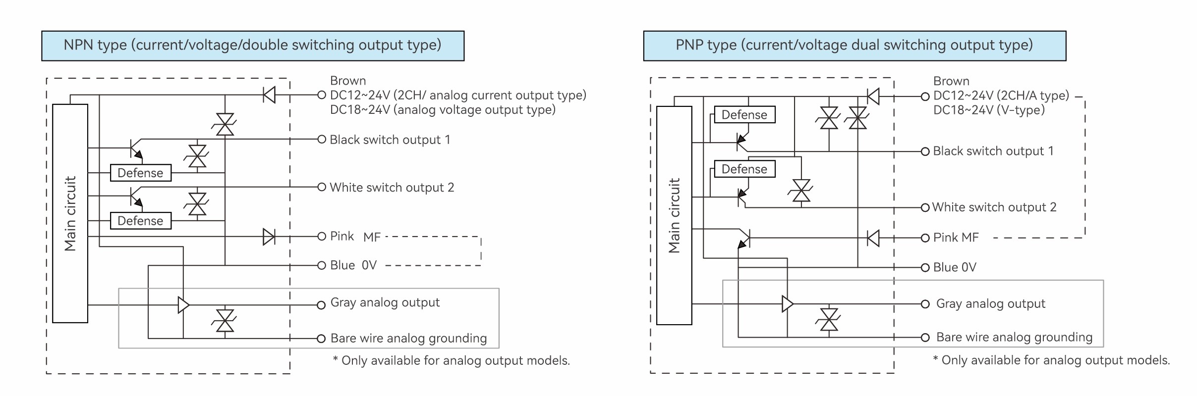
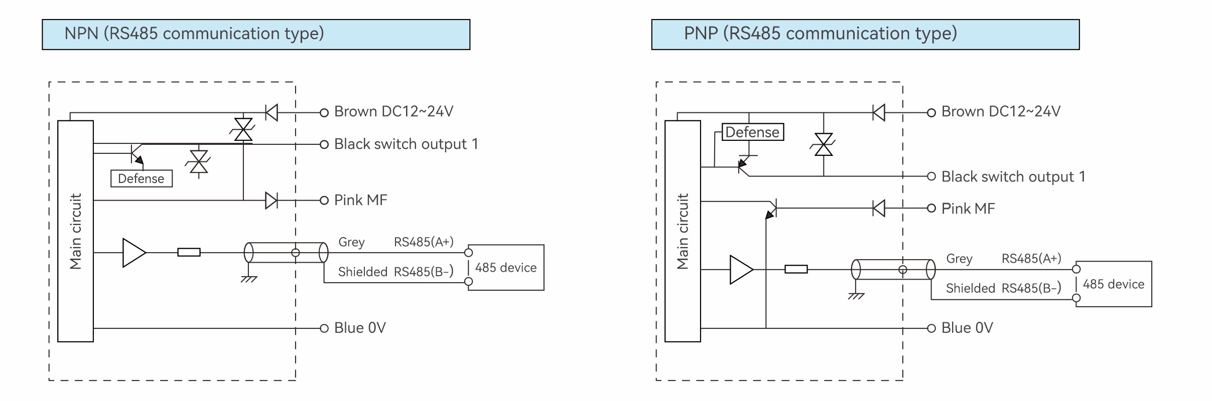
WIRING DIAGRAM
current/voltage/double switching output type
RS485 communication type
MF input (Multi-function input)
In the menu external input select: Zero, Teach, Stop laser.
NPN type: Grey MF wire connected to the negative terminal of the power supply (0V) is more than 20ms and disconnected for triggering once.
PNP model: The grey MF wire is connected to the positive electrode of the power supply (24V) for more than 20ms and disconnected for triggering once.
Note 1. Check whether the cables are correctly connected before switching on the power. In particular, the white line (analog output line) must not touch other lines.
Note 2. The blue wire (0V) and the shielded wire (mode is not grounded) are connected in the internal circuit.
However, please use the blue wire (OV) to connect the negative terminal of the power supply, and the shielded wire (analog ground) is used to simulate the output.
DOCUMENTS & DOWNLOADS
CATALOGUE
3D

