How to Use Contact Displacement Sensors in High-Precision Detection Applications
- Share
- publisher
- Zoe
- Issue Time
- Feb 24,2025
Summary
This solution leverages high-precision contact-type displacement sensors, real-time data monitoring, and automated control to provide an efficient, stable, and precise measurement system for manufacturers. By implementing proper installation, wiring, and maintenance practices, companies can ensure better production control, improved product quality, and higher efficiency across industrial applications.
How to Use Contact-Type Displacement Sensors in High-Precision Detection Applications
Contact-type displacement sensors (such as inductive, LVDT, and pneumatic sensors) are widely used in various industrial fields, particularly in precision manufacturing, machining, quality control, and online detection. With their high-precision displacement measurement capabilities, these sensors effectively detect minute dimensional changes, form and position tolerances (such as roundness, straightness, perpendicularity, and concentricity), and other geometric features. This solution integrates best practices for using contact displacement sensors to provide a high-precision industrial detection solution.
Contact-Type Displacement Sensors Application Scenarios
1. Automotive Component Inspection: Detecting outer diameter, inner diameter, roundness, flatness, and concentricity of bearings, gears, shafts, and other parts.
2. Electronic Product Casing Measurement: Checking the dimensions and form tolerances of phone and computer casings.
3. Glass Industry Inspection: Measuring the thickness, straightness, and perpendicularity of glass surfaces.
4. In-Process Precision Machining Monitoring: Real-time monitoring of part shapes and dimensions during machining to ensure compliance with specifications.
Contact-Type Displacement Sensors Solution

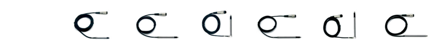
1. Sensor Selection: Contact-Type Digital Displacement Sensor DK-GFW Series
To ensure high-precision measurement, we recommend using the DK-GFW Series Digital Contact Inductive Displacement Sensor, which offers the following features:
▪️Resolution: 0.1 μm for detecting extremely small displacement variations.
▪️Drive Mode: Spring-loaded mechanism, suitable for high-frequency and high-precision measurement.
▪️Multi-Interface Support: Compatible with MODBUS protocol via RS485 and IO interface, allowing easy integration with PLC or upper-level data acquisition systems.
▪️Measurement Capabilities: Suitable for displacement, vibration, inner/outer diameter, perpendicularity, roundness, and straightness detection across multiple industries.
| Model (Thousandth) | DK-GFK-02 | DK-GFK-05L | DK-GFK-05S | DK-GFK-10L | DK-GFK-10S | DK-GFK-10P |
| Resolution | 1 μm | |||||
| Repeatability | 1 μm | |||||
| Measuring Force | 0.9 N | 0.6 N | 0.5 N | 0.8 N | 0.8 N | min 0.2 N |
Model (Ten-thousandth) | DK-GFW-02 | DK-GFW-05L | DK-GFW-05S | DK-GFW-10L | DK-GFW-10S | DK-GFW-10P |
Resolution | 0.1 μm | |||||
Repeatability | 0.3 μm | 0.5 μm | 0.5 μm | 1 μm | 1 μm | 1 μm |
Measuring Force | 0.9 N | 0.6 N | 0.5 N | 0.8 N | 0.8 N | min 0.2 N |
Supported Communication Methods | RS485 / IO | |||||
Linearity | ±0.1%F.S | |||||
Measuring Range | 2 mm (±1) | 5 mm (±2.5) | 5 mm (±2.5) | 10 mm (±5) | 10 mm (±5) | 10 mm (±5) |
Drive Mode | Spring-Loaded | Spring-Loaded | Spring-Loaded | Spring-Loaded | Spring-Loaded | Pneumatic Push |
Wiring Method | Straight Type | Straight Type | L-Type | Straight Type | L-Type | Straight Type |
Excitation Frequency | 13 kHZ | |||||
Operating Temperature | -10 ~ 80 °C | |||||
Fatigue Life | 15 million cycles | |||||
Protection Rating | IP65 | |||||
Probe | Standard probe (optional) | |||||
Housing Material | Stainless steel | |||||
Guiding Device | Ball bearing | |||||
Protective Rubber Sleeve | Fluoroelastomer | |||||
Cable Length | 2 m (customizable) | |||||
2. Installation and Wiring
Sensor Installation:
▪️The sensor should be securely mounted near the workpiece using a magnetic base.
▪️The sensor probe must be perpendicular to the measurement surface to avoid errors and ensure longer sensor life.
▪️Contact force should be kept within the sensor’s rated range to prevent damage.
Electrical Wiring:
▪️Signal wires should be routed separately from high-power lines to prevent electromagnetic interference.
▪️Shielded cables should be used to connect the sensor to the controller, ensuring stable signals.
▪️Grounding Requirements: The sensor casing should be properly grounded, with a ground resistance of less than 1Ω to eliminate static and high-frequency interference.
3. Measurement Process
(1) Preparation: Select appropriate measurement parameters based on the type of workpiece (e.g., outer diameter, inner diameter, roundness).
(2) Sensor Activation: The contact displacement sensor is powered on, initiating real-time measurement of the workpiece dimensions.
(3) Data Acquisition: Measurement data is transmitted via MODBUS RS485 to the PLC or upper-level system for real-time monitoring.
(4) Data Analysis:
▪️The upper-level system analyzes measurement data to determine whether the workpiece dimensions meet tolerance requirements.
▪️If deviations are detected, an alarm is triggered, and adjustments can be made to the manufacturing process.
(5) Online Inspection:
▪️Sensors continuously monitor workpiece dimensions during production.
▪️Ensures consistent quality control and minimizes manufacturing defects.
4. Key Considerations
▪️Contact Pressure: Ensure that applied contact pressure does not exceed the sensor’s rated limits to avoid measurement errors or damage.
▪️Probe Alignment: Always mount the probe perpendicular to the workpiece surface to prevent installation-related errors.
▪️Rubber Bellows: Regularly inspect for deformation in the sensor’s rubber bellows. If deformed, adjust them to restore their normal shape.
▪️Interference Prevention:
• Use a grounded mounting bracket and shielded cables to minimize static and high-frequency interference.
• If static interference occurs, a simple test involves shorting the sensor’s housing screw to a metal point on the machine. If the interference disappears, the issue is static-related.
▪️Air Supply for Pneumatic Sensors: Ensure that the air supply is free from dust, moisture, and oil to prevent contamination.
▪️Maintain Proper Air Pressure: Avoid insufficient supply pressure, as long pipelines or additional pneumatic components (such as needle valves, speed controllers, or microfilters) may cause pressure drops.
5. Real-Time Monitoring and Reporting
By integrating contact displacement sensors with an upper-level system, manufacturers can achieve real-time data collection, storage, analysis, and reporting. Operators can view measurement results via a visual interface, while automatic error detection ensures that any deviation triggers an alarm and corrective actions.
Related Displacement Sensors

Range: 10mm(±5mm)
Repeat accuracy: < 1μm
Linearity: ±0.4% F.S
Measurement force: min 0.2N

Measuring range: 0-25.4 mm
Resolution: 0.2μm
Accuracy: ≤1.8μm
Response time: 50ms

Response time: up to 1.5ms
Repetitive accuracy: up to 10µm

Response time: up to 1.0ms
Repetitive accuracy: up to 2µm