Industrial Safety Mat Sensors for Machine Protection: Crush-Proof, Durable, and Ready for Automation Safety Systems
- Share
- publisher
- Zoe
- Issue Time
- Jun 9,2025
Summary
DADISICK industrial safety mat sensors provide reliable foot-detection for machine safety applications. Crush-resistant, IP65-rated, and compliant with ISO 13849-1, ideal for robot cells, press machines, and smart factories.
What Are Industrial Safety Mats for Machines?
A Pressure‑Sensitive Safety Device
An Industrial Safety Mat (also known as a safety pressure mat) is a pressure-sensitive safety device: when a preset minimum weight is applied, the mat acts as a switch and sends a stop signal to the controller, which immediately halts the protected machinery. This ensures effective protection for operators against potential hazards.
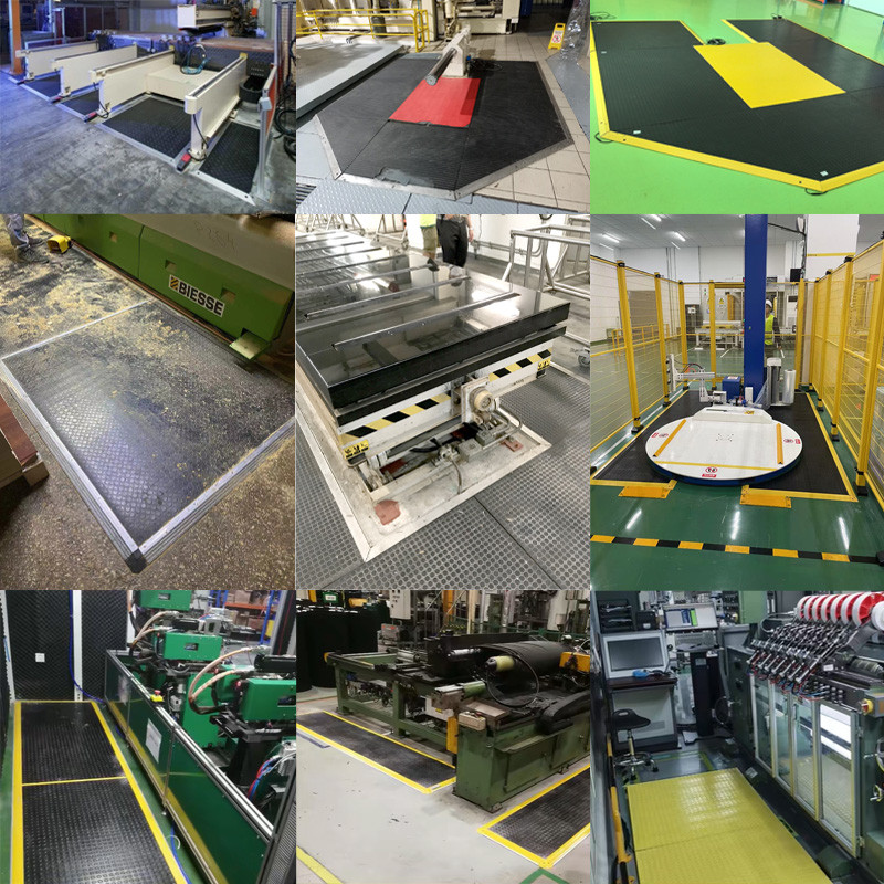
Applications of Safety Mats for Machines
These mats provide area protection around equipment like:
• Welding robots
• Rubber & plastic machines
• Assembly lines
• Material handling systems
• Packaging and press machinery
• Automotive production
• Steel and metallurgical operations
Compared to physical guards, sliding doors, or pull-back stops, industrial safety mats offer freedom, flexibility, and effort savings. They preserve full visibility and accessibility of the workspace while enhancing safety and reducing injury risk.
Core Features of Industrial Safety Mats
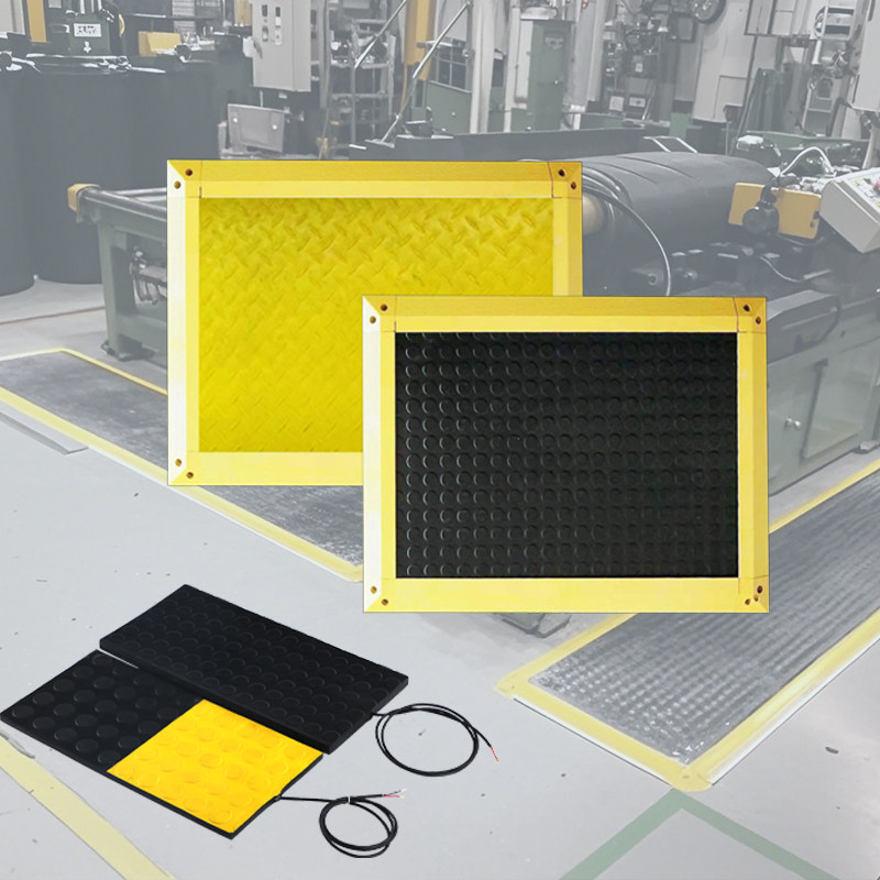
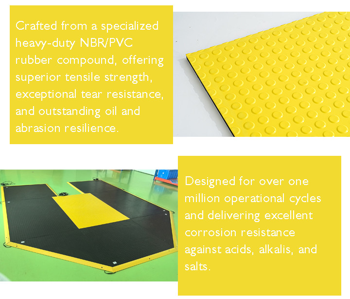
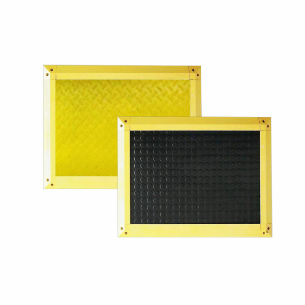
DADISICK safety mats are constructed from heavy-duty PVC or NBR, featuring die-cast impact-resistant structures. They resist delamination and corrosion caused by acids, alkalis, and salts. DADISICK's DK-DT series support loads between 200‑400 N/cm² (strong enough to withstand light vehicle crushing). With expected lifetimes of over 1–3 million cycles and omnidirectional installation capability, they are durable and adaptable.
Standard sizes are limited to ≤1.5 m². For larger areas, multiple mats can be seamlessly assembled.
How Safety Pressure Mats Work
The Principle of Pressure-Sensitive Detection
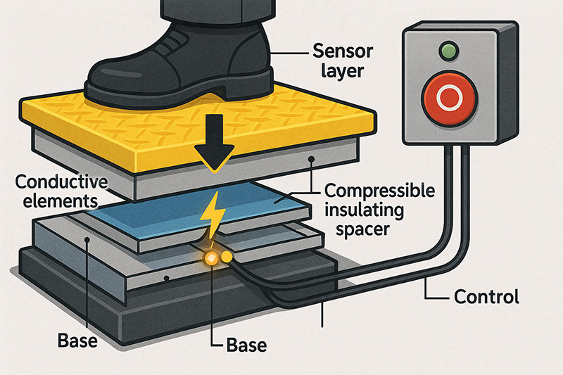
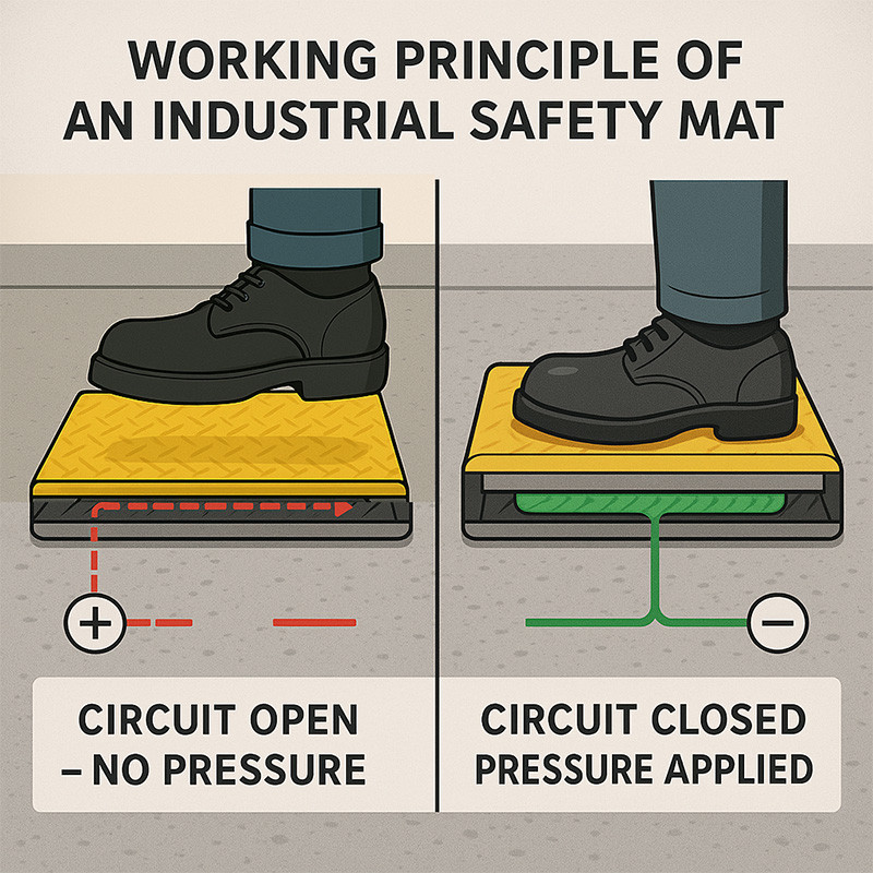
The sensor layer in industrial safety mats operates on the principle of pressure-sensitive detection, where physical pressure or presence on the mat triggers an electrical response to initiate safety measures (e.g., stopping machinery or sounding an alarm).
The sensor layer detects pressure by completing or altering an electrical circuit when weight is applied. It typically consists of two conductive layers separated by an insulating or spacer material. When pressure (e.g., a person stepping on the mat) compresses the layers, they make contact, closing the circuit and sending a signal to a control system.
Key Components and Mechanism
1. Conductive Layers:
● Made of materials like metal plates, conductive foam, or embedded wire grids.
● One layer acts as a "top" conductor and the other as a "bottom" conductor.
● These are normally separated to keep the circuit open.
2. Insulating/Spacer Layer:
● A non-conductive material (e.g., foam or rubber) keeps the conductive layers apart when no pressure is applied.
● Designed to compress under a specific weight threshold (e.g., 20-50 kg, depending on the mat's sensitivity).
3. Circuit Closure:
● When pressure is applied, the spacer compresses, allowing the conductive layers to touch.
● This closes the circuit, generating an electrical signal (e.g., a low-voltage DC or AC signal).
4. Signal Transmission:
● The closed circuit sends a signal through connected wiring to a control unit.
● The control unit interprets the signal and triggers actions like stopping machinery, activating an alarm, or logging the event.
Types of Sensor Mechanisms
● Single-Zone: The entire mat acts as one sensor, triggering a uniform response.
● Multi-Zone: Segmented conductive areas allow detection of specific zones, enabling more complex control (e.g., different responses based on where pressure is applied).
● Capacitive Sensing (Less Common): Some mats detect changes in capacitance caused by a person’s presence rather than physical pressure, used in specialized applications.
Integration of Industrial Safety Mats in Machinery
Layout Planning for Safety Mats for Machines
Industrial safety mats are installed around equipment to form a protective perimeter. When someone steps onto the mat, the piezoresistive sensor captures the pressure and converts it into an electrical switch signal. This signal is relayed to a safety relay or controller, prompting instantaneous machine shutdown before body contact with moving parts—ensuring operator safety.
Typical placement includes
1. Entry points to presses, bending machines, or robotic zones
2. Operator load/unload areas
3. Zones inadequately covered by light curtains
Key layout considerations
• Proper sizing and positioning to cover all risk zones
• Avoid creating trip hazards while maintaining responsiveness
• Seamless coordination with other safety systems
Mats integrate with safety relays (e.g., DK-TER-A), creating compliant systems per EN 1760‑1, ISO 13856‑1, EN 62061, ISO 13849‑1, IEC 61508, EN 60204‑1.
Collaborative Safety: Safety Switch Mats and a Comprehensive Safety Network
Safety switch mats don’t operate in isolation—they’re part of layered safety systems. When combined with light curtains, interlock switches, safety relays, and emergency stop buttons, they offer redundancy and wider protection coverage.
• Mats guard the lower levels while light curtains protect the upper body
• Safety relays consolidate inputs from mats, doors, and E-stops for safe logic decision-making
• With PLC integration, safety mat wiring diagrams facilitate diagnostics, real-time monitoring, and zoned safety management
This integrated system ensures operators are protected regardless of entry point, fulfilling global safety requirements under ISO 13849 and OSHA.

Installation and Wiring Guide for Industrial Safety Mats
Overview of Safety Mat Wiring Principles
Safety mats are essential components in industrial safety systems, designed to protect personnel by detecting pressure and triggering safety responses. They operate on a normally open circuit principle: when no pressure is applied, the circuit remains open, and no current flows, indicating a safe state. When pressure is applied—such as a worker stepping on the mat—the circuit closes as conductive layers within the mat connect, allowing current to flow. This closure signals a safety relay or controller, which monitors the circuit and initiates actions like stopping machinery or activating alarms to ensure safety.
The wiring process involves connecting the safety mat to a safety relay or controller, which interprets the circuit's state and executes the appropriate response. Proper wiring is critical to avoid false triggers (unintended activations) or failures (lack of response when needed). To ensure reliability, installers must follow manufacturer guidelines, use suitable cables, secure connections, and perform regular testing. In essence, the effectiveness of safety mats hinges on their simple yet precise wiring design, making meticulous installation and maintenance vital for industrial safety.
Example Analysis of Safety Mat Wiring Diagram
Safety mats support two main wiring configurations: four-wire and resistor-style (two-wire). The choice depends on the application’s safety and operational needs, and users should confirm compatibility with the manufacturer before purchase.
1. Four-Wire System
1. Four-Wire System
● Description: Uses four wires, with two connected to each internal switch, linked to the safety relay’s dual-channel inputs.
● Advantages: Offers superior stability and fault detection, as the relay monitors each switch independently.
● Use Case: Ideal for high-risk settings requiring maximum reliability, such as large machinery zones.
2. Resistor-Style (Two-Wire) System
● Description: Employs two wires with a terminating resistor, allowing the relay to monitor circuit integrity via resistance changes.
● Advantages: Simpler and more cost-effective, suitable for less complex applications.
● Use Case: Works well in basic setups where advanced fault detection is less critical.
The four-wire system is often recommended for its robustness, though both methods are viable when matched to the right scenario.
3. Wiring Diagram Example
Consider the DK-DT14 series safety mat (Normally open type) and DK-Ter-A safety relay as an example. The DK-DT14 mat is designed for durability and sensitivity (trigger force: 30 kg), while the Ter-A relay supports versatile safety inputs and reset options.
3. Wiring Diagram Example
Consider the DK-DT14 series safety mat (Normally open type) and DK-Ter-A safety relay as an example. The DK-DT14 mat is designed for durability and sensitivity (trigger force: 30 kg), while the Ter-A relay supports versatile safety inputs and reset options.
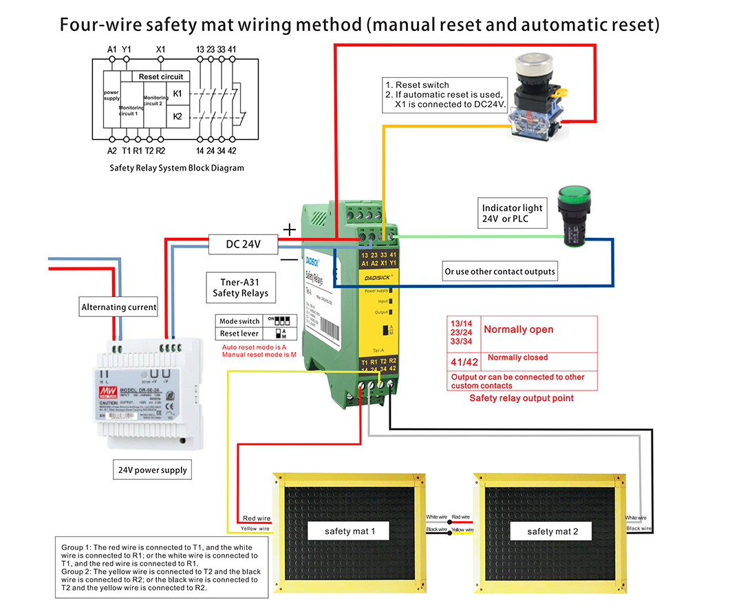

Key Wiring Guidelines for Safety Mats
1. The safety mat must be connected to the dual-channel input terminals (such as OSSD outputs) of a safety relay or a safety PLC to ensure redundant monitoring.
2. Use a 24V DC Regulated Power Supply (Recommended Safe Voltage). Ensure that voltage fluctuations remain within ±10%. The protective earth (PE) wire must be reliably grounded to prevent false triggering caused by electromagnetic interference.
3. Maintain Proper Cable Routing and Shielding
● Keep the signal cables of the safety mat at least 30 cm away from power cables (such as motor or inverter cables).
● If crossing is unavoidable, do so at a 90° angle.
● Use twisted-pair shielded cables, and ground the shielding at one end only (typically at the control cabinet side) to avoid ground loops.
● Prevent cables from being crushed by heavy objects or sharply bent (minimum bending radius should be ≥5 times the cable diameter).
4. Use Crimp Terminals (Twisting Bare Wires Together Is Not Allowed)
After wiring, perform a tensile test—connections must withstand a pull force of ≥15 N
Common Troubleshooting Tips
I. Safety Mat Not Triggering (Device Does Not Stop After Stepping)
Fault Phenomenon | Possible Causes | Troubleshooting Methods | |||
No Response When Stepping on the Safety Mat | 1. Power not connected or insufficient voltage | Use a multimeter to measure the power supply voltage (DC 24V ±10%) and check if the power switch is functioning properly. | |||
| 2. Loose or disconnected wiring | Check the terminal block and plug connections for looseness. Use a multimeter continuity test to check the cables. | ||||
| 3. Internal sensor failure in the mat | Short the mat’s output terminals. If the device stops, the internal circuit of the mat is faulty and the mat needs to be replaced. | ||||
Indicator Light Not On (if available) | 1. Fuse blown | Replace the fuse with one of the same specifications. Check the circuit for short circuits (e.g., exposed wires touching ground). | |||
2. Indicator light failure | Measure the voltage across the indicator light. If voltage is present but the light is off, replace the indicator. | ||||
II. Safety Mat False Triggering (Device Stops Unexpectedly Without Being Stepped On)
1. Electromagnetic Interference
1. Electromagnetic Interference
Cause: Nearby devices such as inverters, welding machines, or other strong electromagnetic sources.
Solution:
● Check if the shielding layer is properly grounded. Try grounding both ends if permitted by the product manual.
● Ensure signal cables are kept at least 30 cm away from power cables and avoid parallel routing.
2. Loose Connections or Short Circuits
Cause: Poor contact at terminals or damaged insulation on cables.
Solution:
● Re-crimp terminals and wrap exposed wire cores with insulating tape.
● Use a multimeter to check insulation resistance (≥10 MΩ); replace any damaged cables.
3. Foreign Objects or Deformation on the Mat Surface
● Cause: Dust, metal debris, or raised mat edges may cause false pressure sensor signals.
Solution:
● Clean the surface of the mat with compressed air.
● Repair or replace any deformed mat strips.
III. Device Does Not Reset After Triggering
III. Device Does Not Reset After Triggering
1. Faulty Reset Button or Circuit
Cause: Poor contact in the reset button or relay stuck in the safety circuit.
Solution:
● Measure voltage at the reset button terminals while pressing. If no NC (normally closed) signal is detected, replace the button or relay.
2. Mechanical Obstruction in the Mat
Cause: Foreign objects (e.g., screws, debris) under the mat prevent the sensor from returning to its original state.
Solution:
● Lift the mat and remove any objects underneath.
● Check if the cushioning layer is aging or deformed; replace if necessary.
Industrial Safety Mats Performance Testing
1. Roll‑Over Pressure Resistance Testing
● EN 1760‑1 / ISO 13856‑1 standards specify that pressure-sensitive mats must reliably detect individuals weighing over 20–35 kg and trigger safety functions accordingly.
● Mats undergo mechanical tests that simulate repeated roll-over pressure from humans or light vehicles to ensure consistent actuation thresholds and long-term durability. These tests ensure the mat reliably triggers a stop after repeated stress cycles.
2. Electrical Insulation & Leakage Testing
● For mats used near electrical equipment, standards such as IS 15652 (India) and IEC 61111 define tests for dielectric strength, insulation resistance, and leakage current under conditions up to 66 kV AC or 240 V DC.
● Dielectric withstand tests (hipot tests) apply high voltage and measure leakage current to confirm the mat’s insulation integrity.
3. Acid & Alkali Corrosion Resistance Testing
● Mats must also resist chemical degradation. Standards like IS 15652 include tests assessing resistance to acids, alkalis, oils, and low temperatures.

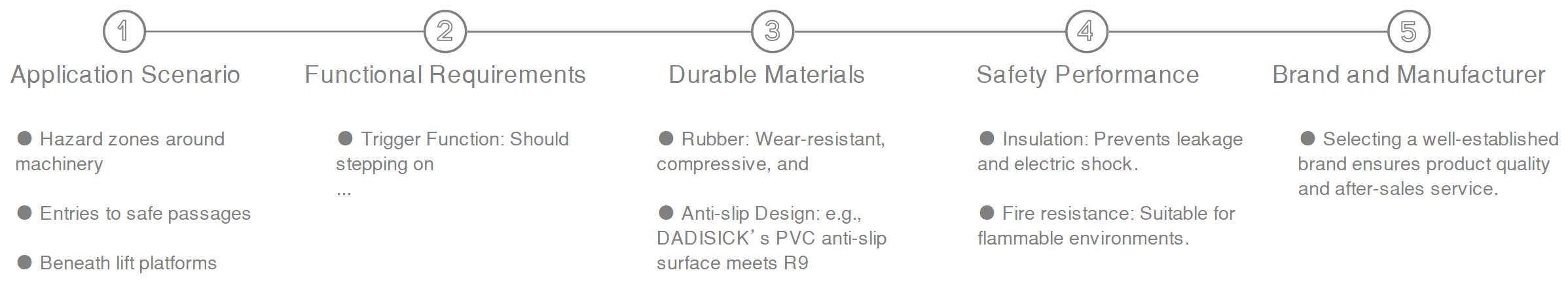
Industrial Safety Mat Selection and Purchasing Guide

| Specifications | |||
| Trigger Force | >20 kg | 30 kg (for adults) | |
| Weight | Maximum Allowable Load (8 hours): ≤ 400 N/cm² | Maximum Allowable Load (8 hours): ≤ 200 N/cm² | Pressure Resistance:
Dynamic load up to 500 kg
Static load up to 700 kg |
| Safety Mat Thickness | 15 mm | 11 mm | 14 mm |
Surface Material | NBR rubber | PVC | NBR rubber |
Mechanical life | 3,000,000 times | 1,000,000 times | 1,000,000 times |
Degree of protection | IP65 | ||
Ambient temperature | -10℃ ~ +55℃ | +5℃ ~ +55℃ | -10℃ ~ +60℃ |
Response time | 18 ms | < 30 ms | |
Recommended applications | Special or heavy-duty working conditions | General working conditions; | Safety protection for people,
small cars and vehicles in mixed areas |
Related Safety Products
Detection Method: Pressure sensing method
Pressure Resistance: Dynamic load up to 500kg, static load up to 700kg
Trigger Force: 30 kg (for adults)
Surface Protection Material: NBR rubber
Mat Thickness: 14 mm
Used for monitoring places such as safety doors and windows.

Beam spacing: 30mm
Number of optical axes: 42
Protection height: 1230mm
Safety light curtain outputs (OSSD)2 PNP
5m distance, A technique that uses a laser beam to measure distance and create detailed maps of objects and environments.