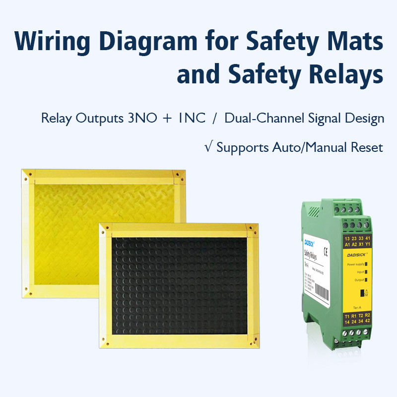
How to Use Safety Relays to Monitor Safety Mats? Wiring Diagrams and Applications
- Share
- publisher
- Zoe
- Issue Time
- May 7,2025
Summary
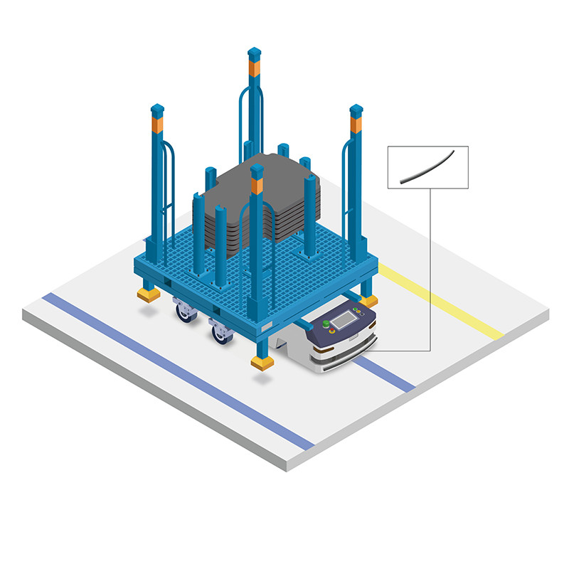
A safety mat is a presence-sensing safety device (PSSD) containing internal pressure switches. When a person steps onto the mat, these switches close; when the person leaves, the switches open, thereby generating an on-off signal that is sent to a safety relay. Together, the safety mat and the safety relay form part of a safety system designed to detect presence in a hazardous area.
A safety mat, by itself, functions solely as a presence detection device. It closes its internal switch when someone steps into a hazardous area but does not possess complete fault monitoring and safety shutdown capabilities. Therefore, it needs to be connected to a dedicated safety relay or mat controller to meet the requirements of safety standards such as ISO 13849-1 and IEC 62061. This enables reliable dual-channel redundancy, safety shutdown, fault bypass prevention, and automatic/manual reset functions. Consequently, when a hazard is detected, machine movement can be quickly and safely interrupted, preventing personal injury or equipment damage.
Basic Principles of Safety Mats
Presence Sensing Function
A safety mat is a presence-sensing safety device (PSSD) with internal pressure switches. When personnel stand on the mat, the switches close; when personnel leave, the switches open, generating an on-off signal.
No Monitoring Capability
A standalone safety mat does not have the ability to monitor for open or short circuits in its wiring, nor can it guarantee redundancy and sensitivity on the switch side. It cannot meet the "circuit integrity" and "fault detection" requirements for high-level safety functions.
Why Do Safety Mats Need to Be Connected to Safety Relays?
1. Fault Detection and Circuit Monitoring
A safety relay can actively detect faults such as open or short circuits in the wiring connected to the safety mat. Upon detecting an anomaly, it issues a safety stop command to prevent hazardous operating conditions.
2. Dual-Channel Redundant Design
Compliant with the Performance Level (PL) requirements of ISO 13849-1 and the SIL level requirements of IEC 62061, safety relays typically employ a dual-channel or dual-coil design. This ensures that the failure of a single path does not affect the overall safety function.
3. Safety Stop and Reset Control
When the mat detects someone stepping on it, the safety relay immediately cuts off the drive power through its output contacts, achieving a safety stop. After the person is removed, automatic or manual reset can be selected as needed to prevent accidental restart.
4. Bypass Prevention and Self-Checking Function
Safety relays feature internal mutual monitoring, self-checking circuits, and bypass prevention designs. Even if someone attempts to short-circuit the mat circuit, the system cannot be deceived, thus preventing the safety function from being bypassed.
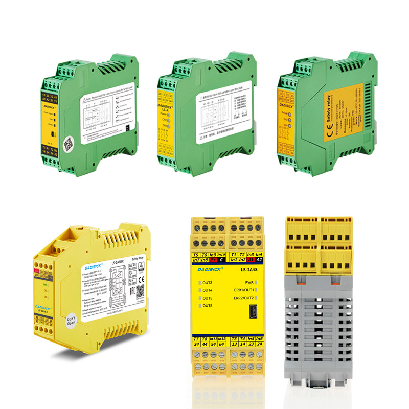
Typical Functions of Safety Relays
| Function | Purpose | ||||
Fault Monitoring (Open/Short Circuit Detection) | Ensures circuit integrity; initiates immediate shutdown upon line abnormalities. | ||||
Dual-Channel Redundant Output | Meets high safety level requirements such as PL d/SIL 3; failure of a single path does not affect the overall system. | ||||
| Safety Stop Output | Quickly cuts off power to eliminate hazards. | ||||
| Automatic/Manual Reset | Provides flexible reset methods to prevent accidental restart of personnel or equipment in hazardous conditions. | ||||
| Bypass Prevention Design | Prevents users from bypassing the safety circuit using jumpers or other methods. | ||||
System Diagnostics and Indicator Lights | Provides real-time feedback on circuit status, facilitating maintenance and troubleshooting. | ||||
In addition, there are dedicated Mat Controllers available on the market, such as the Allen-Bradley MatGuard™ control unit. These integrate monitoring, redundancy, and reset functions and can directly manage multiple safety mats and output standardized safety stop signals.
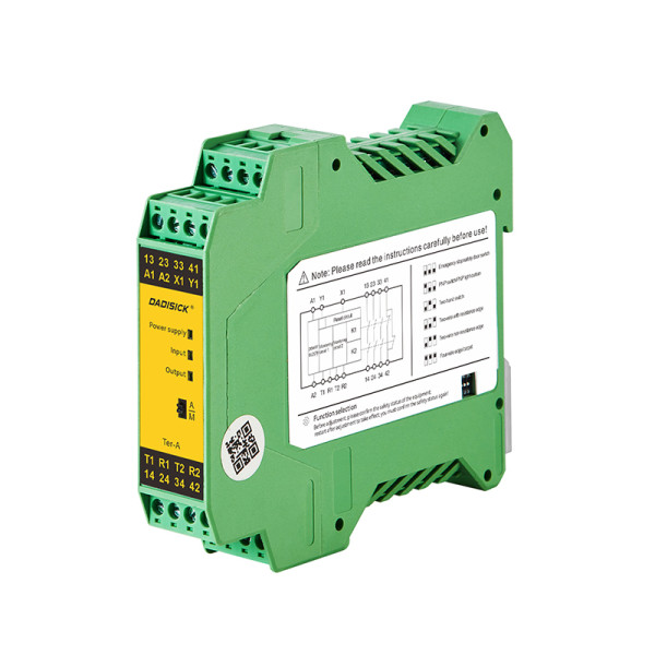
Safety Relay Wiring Examples and Industry Practices
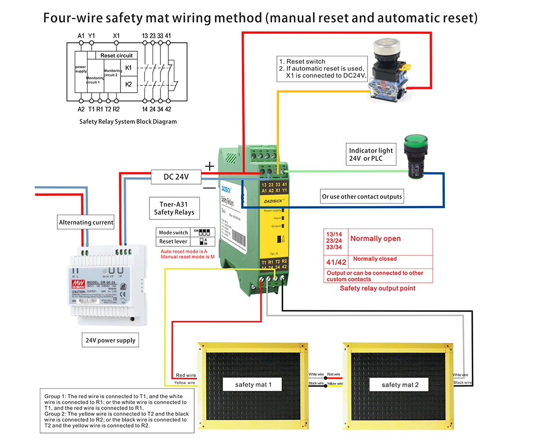
In practical wiring, safety mats are typically connected to the dual-channel input terminals of a safety relay using either a four-wire or two-wire configuration. The relay then controls isolation contactors or drive circuits through two independent safety output contacts, achieving the disconnection of power to the hazardous parts.
Safety Mat - 4-Wire Simplified Wiring Diagram
Safety mats can be wired using either a four-wire method or a method incorporating resistors. Users can choose either wiring configuration, although the four-wire method generally offers greater stability. Safety relays typically provide options for automatic or manual reset. Manual reset is generally preferred for enhanced safety. If the safety relay is connected to a PLC that has a reset function, automatic reset on the safety relay may be used.
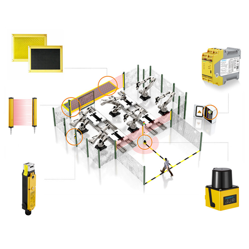
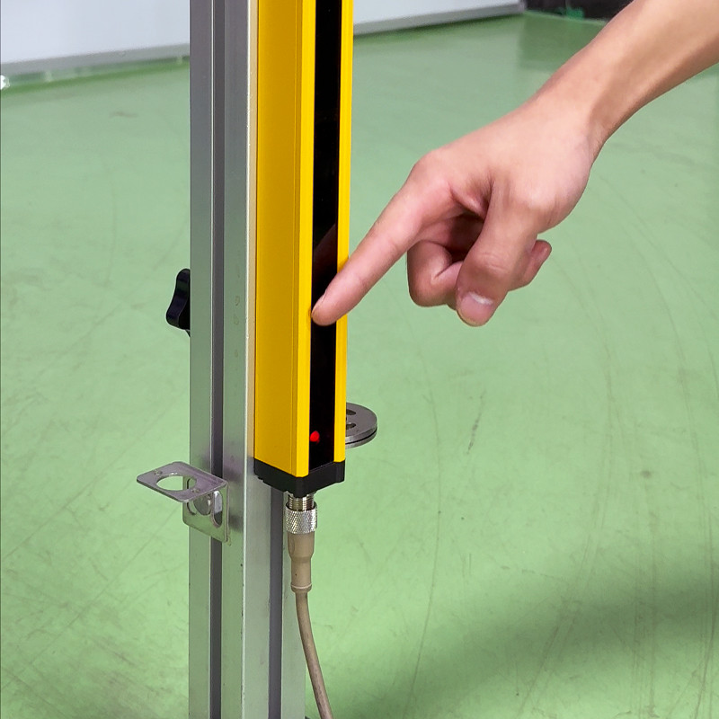
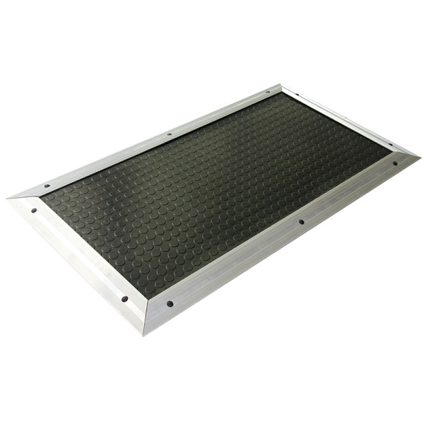
Related Safety Devices
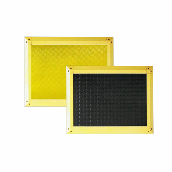
Detection Method: Pressure sensing method
Pressure Resistance: Dynamic load up to 500kg, static load up to 700kg
Trigger Force: 30 kg (for adults)
Surface Protection Material: NBR rubber
Mat Thickness: 14 mm
Detection Method: Pressure sensing method
Maximum allowable load (8 hours) ≤ 400 N/cm²
Trigger Force: >20 kg
Surface Protection Material: NBR rubber
Mat Thickness: 15 mm