Safety Edge Sensor Troubleshooting & Fix: Installation Guide and International Brand Compatibility
- Share
- publisher
- Zoe
- Issue Time
- Jun 2,2025
Summary
Troubleshoot and fix safety edge sensors with our step-by-step installation guide, and discover seamless compatibility with other brands using DADISICK solutions.#electrical safety edge #gate safety edge sensor #sensing edges

What Is a Safety Edge Sensor?

Definition & Working Principle
A safety edge sensor (also called a safety edge strip) is a pressure-sensitive device installed on the edges of doors, gates, or machinery to detect contact with an object or person. When the strip is compressed (for example, by a hand, foot, or other obstacle), it sends an electrical signal to the control unit, which immediately triggers a stop or reverse action. This real-time response ensures that equipment—such as sliding doors, industrial presses, or automated conveyors—stops before causing injury or damage.
Types of Safety Edge Sensors:
1. Pressure-sensitive rubber strips (most common)
2. Air pressure (pneumatic) safety edges
3. Photoelectric (light-based) safety edges
Typical Applications:
1. Industrial door edges or gate edge sensor (warehouse dock doors, automated factory gates)
2. Elevator and escalator emergency stops
3. Automated machinery (press brakes, robotic cells)
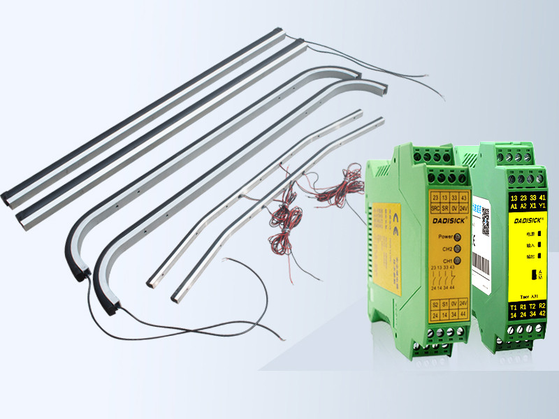
Primary Components
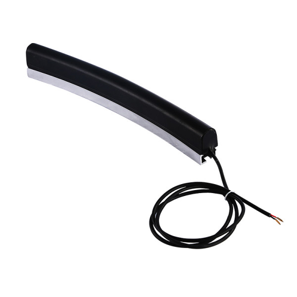
1. Safety Edge Strip (Sensor Element):
● A rubber or polyurethane extrusion containing a conductive layer or air channel.
● Mounted directly on the moving edge; available in various profiles (15 mm, 25 mm, 35 mm widths, etc.).
2. Control Unit / Interface Module:
● Interprets the raw signal from the safety edge strip.
● Either built into a dedicated safety relay or connected to a machine’s PLC safety input.
3. Mounting Hardware & Accessories:
● Brackets, channels, end caps, and screws for proper alignment and weatherproofing.
Why Safety Edge Sensors Matter
1. Compliance: Meets international safety standards such as ISO 13849-1 (Safety of Machinery) and IEC 62061 (Functional Safety).
2. Liability Reduction: Prevents severe injuries, lawsuits, and regulatory fines.
3. Operational Efficiency: Minimizes unplanned downtime caused by accidents.
Common Safety Edge Faults & Causes
Typical Safety Edge Fault Symptoms
When a safety edge sensor fails or malfunctions, you might notice:
1. No Response / No Trigger Signal: The door or machine does not stop when pressure is applied to the edge.
2. False Triggers / “Ghost” Activations: The system stops or reverses without any physical contact—often due to electrical noise or environmental factors.
3. Intermittent Operation: The sensor works sometimes but fails unpredictably, leading to unreliable safety behavior.
4. Continuous “Pressed” Status: The control unit always reads the edge as “activated,” preventing normal operation.

Common Causes of Faults
1. Physical Damage to the Safety Edge Strip:
● Wear & Tear: Over time, repetitive compression can crack the rubber extrusion or break internal conductors.
● Sharp Impacts: If a heavy object strikes the edge, it can dent or puncture the strip, compromising the internal wiring or air channel.
● Moisture Ingress: In outdoor or high-humidity environments, water can seep inside and short-circuit the sensor element.
2. Wiring & Connector Issues:
● Loose Terminals / Loose Crimps: Vibration and movement can loosen screw terminals or crimped wire connectors, causing intermittent signals.
● Abrasion / Cable Damage: Running through metal conduit or sharp corners without proper strain relief can nick the cable jacket, exposing conductors.
● Short Circuits / Open Circuits: A bare conductor touching ground or a broken wire inside the jacket can lead to no output or false activations.
3. Control Unit & Relay Problems:
● Relay Contact Wear: Within a safety relay, repeated switching can erode contacts, leading to sluggish or failed outputs.
● Internal Module Failure: Electronics in the interface module can fail due to heat, voltage spikes, or manufacturing defects.
● Incorrect Wiring / Improper Grounding: Miswired safety inputs or lack of a proper ground reference can mislead the module into thinking the edge is pressed.
4. Environmental & Installation Factors:
● Extreme Temperatures: Rubber compounds can become brittle at low temperatures or excessively soft at high temperatures, affecting sensitivity.
● Debris & Dust Buildup: Accumulated dirt between the edge and machine frame can hold the sensor partially compressed, simulating a “pressed” state.
● Electromagnetic Interference (EMI): Nearby motors, welders, or high-voltage lines can induce noise onto the safety edge cable, causing false trips.
Tip: Before beginning troubleshooting, always consult the original wiring diagram or manufacturer’s datasheet to confirm proper terminal assignments and rated voltages.
Safety Edge Sensor Troubleshooting & Fix

Troubleshooting Wired Safety Edge Systems
Step 1: Preliminary Safety Checks
1. Power Down & Lockout: Ensure the entire system is de-energized and locked out following your facility’s LOTO (Lock Out Tag Out) procedure.
2. Visual Inspection: Scan the entire length of the safety edge strip/button for visible damage (cuts, cracks, abrasions). Check connectors for corrosion or signs of water ingress.
Step 2: Test the Edge Strip Itself
Step 2: Test the Edge Strip Itself
1. Continuity Test with a Multimeter:
● Set the meter to the resistance (Ω) function.
● Disconnect the safety edge from the control unit.
● Place probes on the two output wires; with no pressure, the resistance should read “Open” (infinite Ω) for normally open (NO) edges or “Closed” (≈ 0 Ω) for normally closed (NC) edges.
● Press the strip; for NO edges, resistance should drop to ≈ 0 Ω; for NC edges, it should rise to “Open.” If not, the strip is likely damaged or internally shorted.
2. Check the Cable Jacket:
● Slide the outer jacket back (if possible) and inspect for broken conductors.
● Wiggle the cable near the edge strip and listen/observe the multimeter for fluctuations, indicating a frayed wire.
Step 3: Inspect Connectors & Wiring
1. Tighten Screw Terminals: Loose screws can introduce intermittent faults.
2. Look for Pinched Wires: Remove any cable grommets and verify the wires inside are fully seated in their terminals.
3. Measure Voltage at the Control Unit Input:
● Power on the control module briefly, set the multimeter to DC volts, and check the safety input terminals.
● Power on the control module briefly, set the multimeter to DC volts, and check the safety input terminals.
● A stable 24 VDC (or rated voltage) should be present across the input when the edge is not pressed. If the voltage fluctuates, the issue may be upstream (power supply problem) or due to EMI.
Step 4: Check the Control Unit / Safety Relay
1. Relay Contact Test: With the safety edge disconnected, press the test pushbutton on the relay (if available) to manually simulate a trip. Listen for the relay to click, and use a meter to confirm the output contacts change state. If the relay does not respond or the contacts remain welded, the relay module itself needs replacement.
2. Module LEDs & Indicators: Many modern safety relays have status LEDs (Power, Safe, Trip, Fault). Reference the user manual to interpret LED blink codes—this can pinpoint short circuit, open circuit, or internal fault conditions.
Step 5: Environmental & EMI Checks
1. Shielded Cable & Grounding: Confirm the safety edge cable is shielded and that the shield is properly grounded at one end only (usually at the control unit).
2. Relocate Cables: If the cable runs parallel to power conductors or near variable-frequency drives (VFDs), reroute it at least 6 in (15 cm) apart to minimize EMI.
3. Clean the Surroundings: Remove accumulated dust or debris from around the edge mounting area. A simple brush or canned air can free up material that causes false activations.

Safety Edge Sensor Fix & Replacement
Once you’ve identified the root cause, follow these repair steps:
1. Repair or Replace the Safety Edge Strip (“Safety Edge Strip”)
● Minor Damage (Small Cuts/Cracks):
(1) Use high-quality silicone sealant to fill small cracks and allow 24 h to cure.
(2) Bandage the strip temporarily with heavy-duty waterproof tape to test functionality.
(3) Note that this is a short-term fix—order a replacement strip as soon as possible.
● Severe Damage (Torn or Severed Strip):
(1) Order a new safety edge strip in the exact width and profile. For international compatibility, ensure the new strip’s electrical rating (e.g., 24 VDC, max. 1 A) matches the control unit.
(2) Measure the mounting channel and cut the new strip to length with a sharp utility knife.
(3) Install end caps and mounting brackets per the manufacturer’s instructions.
2. Replace Damaged Cable or Connector
● Cut out the damaged section of cable, strip insulation, and splice with new, high-flexibility cable using crimp-style butt connectors rated for outdoor use.
● If the OEM connector is damaged, replace it with a new connector of the same pin configuration. Ensure pins are fully inserted and locked.
● Use heat-shrink tubing over splices for added environmental protection.
3. Control Unit / Safety Relay Maintenance
● Clean Relay Contacts: If the relay is serviceable (user-replaceable contacts), open the module per the manual, clean contacts with contact cleaner, and reassemble.
● Replace Faulty Relay Module: If cleaning does not restore functionality, replace the entire safety relay or interface module.
● Firmware Update (If Applicable): Some advanced safety modules allow firmware updates for improved diagnostics. Verify with your vendor’s documentation.
4. Upgrade Using a Compatible Safety Edge Sensor
● If you need to switch brands—e.g., from a ABB or Mayser unit to a DADISICK compatible safety edge sensor—follow these steps:
(1) Identify the original edge’s electrical specs (voltage, current, contact type).
(2) In DADISICK’s compatibility chart, find the matching model (e.g., ABB “TT 25-45 TPE” → DADISICK “DK-DB-PSE-245”).
(3) Cross‑reference mounting dimensions (strip height, profile width) to confirm mechanical fit.
(4) Confirm cable length and connector pinout. If pinout differs, you may need an adapter harness or to rewire the connector.
Pro Tip: Always keep a small stock of spare safety edge strips and cables on-site to reduce downtime—especially if your facility has multiple automated doorways or pressing machines.
Installation & Calibration of Safety Edge Sensors

Selecting the Right Safety Edge Sensor
When choosing a safety edge sensor, consider:
1. Trigger Pressure Range: Typical values range from 15 N to 90 N. Lower pressure (15 N–30 N) is suitable for pedestrian doors; higher pressure (45 N–90 N) is better for heavy industrial equipment.
2. Strip Width & Profile: Common widths are 15 mm, 25 mm, and 35 mm. Match the original profile to fit the mounting channel or bracket.
3. Ingress Protection (IP) Rating: For outdoor or washdown environments, choose IP65 or IP67 to resist water and dust. Indoor applications might allow IP54.
4. Operating Temperature: Ensure the strip’s rubber compound can withstand the ambient range in your facility (e.g., –30 °C to +70 °C for freezers or high-temp kitchens).
5. Electrical Interface: Decide between NPN/PNP dry contact (0 V/24 V) or IO‑Link for smart monitoring.
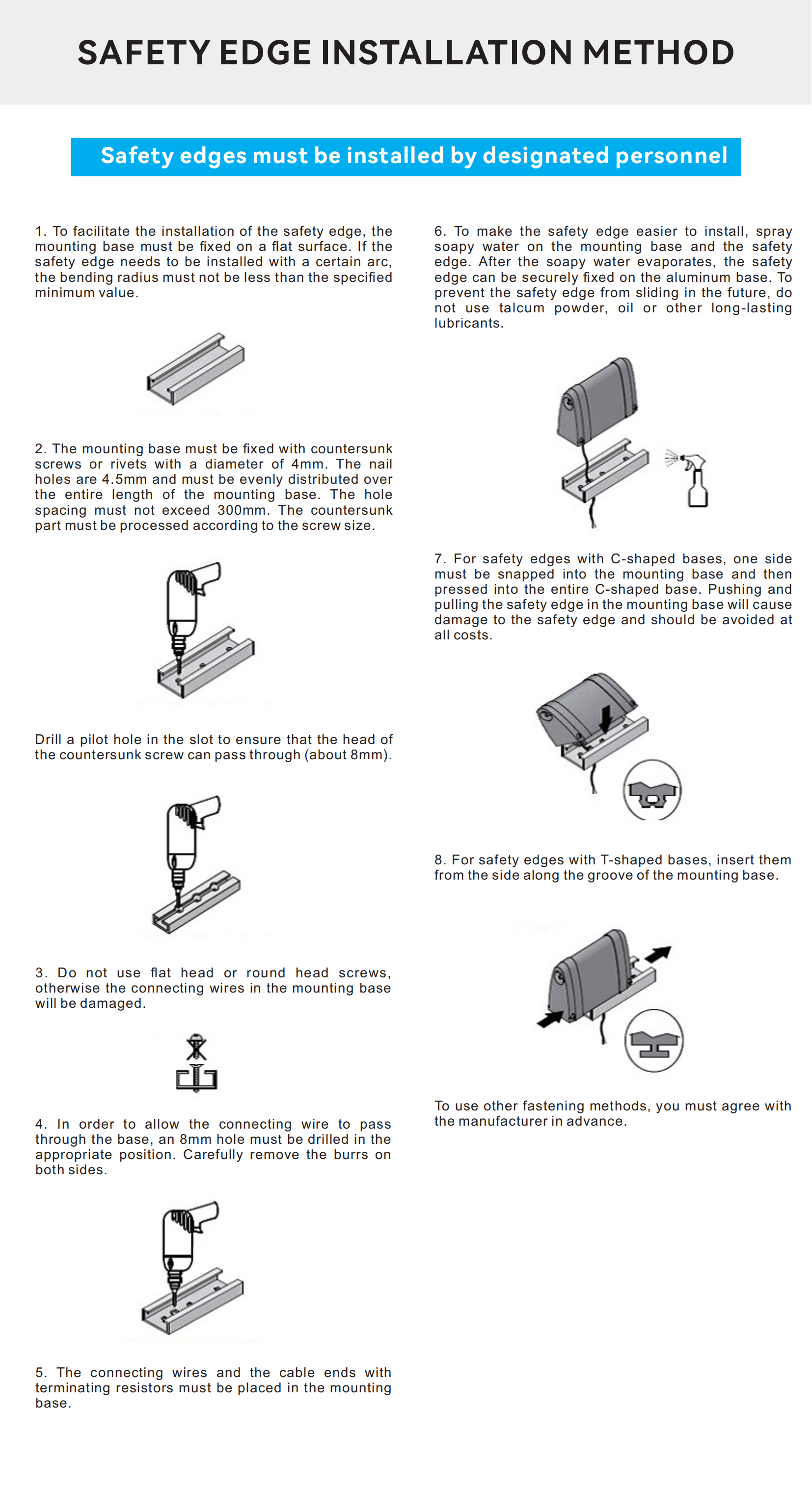
Step‑by‑Step Installation Guide
1. Preparation & Safety
● Power off the machine or door control cabinet and lock out/tag out per your site’s procedures.
● Gather tools: electric drill, self-tapping screws, measuring tape, screwdriver, wire stripper, multimeter, silicone sealant.
● Lay out the new safety edge strip beside the mounting channel to verify length.
2. Mounting the Safety Edge Strip
● Mark Mounting Points: Use a straightedge and pencil to mark where the strip will sit. Ensure it’s parallel to the moving edge and at a consistent height (usually 10–20 mm from the panel).
● Install Brackets or Aluminum Channels (If Required): Some installations require a U-shaped aluminum channel. Secure the channel with screws spaced every 300 mm.
● Insert the Safety Edge Strip: Push the strip into the channel until it snaps in place. Add end caps provided by the manufacturer.
● Seal Joints: Apply silicone sealant around end caps and any drilled holes to prevent moisture ingress.
3. Connecting to the Control Unit
3. Connecting to the Control Unit
● Wire Routing: Route the cable away from sharp edges and power lines. Use cable ties and protective conduit.
● Wiring Diagram:
(1) Safety edge typically has two conductors (for normally open or normally closed output).
(3) Connect one conductor to the safety input (S1) on the relay/module, and the other conductor to 0 V (ground) or 24 V supply, depending on the module’s design.
● Verify Polarity: If the module expects a normally closed (NC) contact, ensure the strip is wired accordingly; otherwise, the system may register a constant “fault.”
4. Power‑On & Initial Test
● Re‑energize the safety system and observe the safety relay’s LED indicators. A “Safe” LED (green) should be solid.
● Manual Press Test: Gently press the strip at various points. The relay should immediately switch to the “Trip” state (red LED), halting the door or machine. Release the pressure and verify a clean reset.
● Multi‑Point Test: Walk along the entire length of the strip, pressing at least every 100 mm to confirm uniform sensitivity.
Calibration & Fine‑Tuning
1. Adjust Sensitivity (If Available): Some advanced modules allow you to set thresholds for trigger pressure. Use the module’s potentiometer or digital interface to tweak sensitivity if false trips occur.
2. Environmental Compensation: If operating in extreme cold (below –10 °C) or dusty conditions, consider covering the strip with a protective rubber hood or using a polyurethane‑based strip that resists abrasion.
3. Documentation & Labeling: Print a simple wiring diagram and attach it inside the control cabinet. Label the cable as “Safety Edge 1” or “SE‑Door A” for future maintenance clarity.
Maintenance Tip: Schedule quarterly checks—quickly verify continuity with a multimeter and visually inspect for wear. A properly maintained safety edge can last 5–7 years in typical industrial settings.
Comparison: Compatible Safety Edge Sensors vs. International Brands
As a professional safety sensor manufacturer, DADISICK offers safety edge sensors compatible with major international brands like SICK, Keyence, and ABB. Below is a high-level comparison table highlighting key specs:
| Feature / Parameter | ABB | ASO Safety Solutions | Mayser | OMRON | Pepperl+Fuchs | Rockwell Automation | Schmersal | DADISICK |
| Trigger force | 63.4 N - 87.9 | 26 N - 89 N | < 150 N | 42 N - 78 N | 80 N | 13.5 N - 87.0 N | 22 N - 92 N | ≤25N or ≤100N |
| Strip Width (mm) | 30 mm | 15/25/30 mm | 15/25/35 mm | 15/25/35 mm | 25/30 mm | 25 mm | 25/30 mm | 15/25/35 mm |
| Ingress Protection (IP) | IP 65 | IP65 | IP65 / IP67 | IP65 | — | IP67 | IP67 | IP65 |
Material | TPE | TPE / EPDM | EPDM / NBR / CR | TPE / EPDM | EPDM | EPDM / NBR / CR | EPDM | TPE or EPDM |
Operating Temperature | -10 °C to 50 °C | -10° to +55°C | -10 to +55 °C | -10 to 55°C | 5 ... 55 °C | -5…+55℃ | -30°C to 140°C | -20 ℃ - +55℃ |
Mechanical Life Cycles | — | — | — | 1,000,000 cycles min. | — | — | > 20,000,000 | >3,000,000 |
Note: When replacing or integrating DADISICK's DK-DB-PSE series products, it's generally advisable to verify exact model numbers and consult relevant technical datasheets to ensure compatibility. DADISICK's DK-DB-PSE series products are designed to meet or exceed Original Equipment Manufacturer (OEM) specifications and typically achieve drop-in compatibility with most Omron, ABB, and Mayser systems.
FAQs & Further Resources
Frequently Asked Questions
1. Q: Why does my safety edge sensor keep triggering without contact?
A: This symptom usually indicates either (a) accumulated debris or dirt holding down the strip, (b) a loose or shorted cable causing false signals, or (c) excessive electromagnetic interference (EMI) from nearby equipment. Check and clean the strip, tighten all connections, and ensure cable shielding is grounded correctly.
2. Q: Can I temporarily repair a torn safety edge strip myself?
A: For minor tears, you can apply industrial-grade silicone sealant and wrap with waterproof tape to test functionality. However, this is a short‑term workaround—plan to replace the strip with a new safety edge strip that matches the original profile as soon as possible.
3. Q: Are DADISICK’s compatible safety edge sensors a direct fit for my existing mayser system?
A: In most cases, yes. DADISICK publishes a compatibility chart matching Mayser model numbers (e.g., Mayser GP 60-1 EPDM → DADISICK DK-DB-PSE-360). Verify electrical specs (voltage, current) and mechanical dimensions to confirm. If pinouts differ, an adapter wire harness might be required.
4. Q: How do I adjust sensitivity on a wired safety edge system?
A: If your safety relay or interface module supports sensitivity adjustment (usually via a potentiometer or digital setting), carefully increase or decrease the threshold while monitoring for false trips. Always perform sensitivity tuning with the system under normal operating conditions and monitor across the entire strip length.
5. Q: What is the recommended maintenance schedule for a safety edge sensor?
A: At a minimum, visually inspect and test the strip every 3 months. Perform a full continuity test with a multimeter, check for cable damage, and verify the relay’s status LEDs. In more demanding environments (high heat, chemical exposure, heavy traffic), consider monthly checks.
Further Resources & Downloads
Related Safety Sensors
Safety Edges is a technology that monitors the pressure distribution on the carpet through pressure sensing.
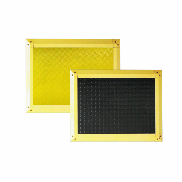
Detection Method: Pressure sensing method
Pressure Resistance: Dynamic load up to 500kg, static load up to 700kg
Trigger Force: 30 kg (for adults)
Surface Protection Material: NBR rubber
Mat Thickness: 14 mm
5m distance, A technique that uses a laser beam to measure distance and create detailed maps of objects and environments.
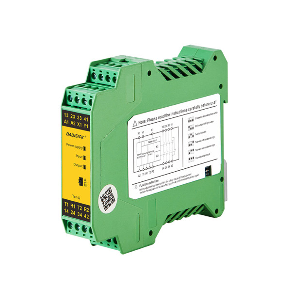
Multifunctional safety relay, providing automatic/manual reset configuration and multifunctional configuration DIP switch, used for industrial field monitoring of various signals with high safety requirements.