Precise Dimensional Measurement Methods for Large Industrial Equipment Stands
- Share
- Issue Time
- Jan 27,2026
Summary
Accurate dimensional measurement of large industrial equipment stands involves unique challenges. This article explains practical measurement methods, key difficulties, and best practices for reliable shop-floor results.


Large equipment stands form the foundation of heavy machinery and precision devices across manufacturing sectors. Ensuring their dimensional accuracy is critical for machine performance, alignment, and product quality. This article explores the key challenges associated with measuring large-scale equipment stands, common sources of error, modern measurement technologies, and best practices to improve efficiency and reliability on the shop floor. Practical insights aim to help engineers and technicians reduce inspection time while increasing measurement accuracy.
What Are Equipment Stands and Why Do They Matter
In industrial facilities, equipment stands serve as the structural base for large machines such as production lines, machining centers, inspection systems, and semiconductor fabrication equipment. These stands must provide rigid support and precise alignment to ensure that the machines mounted on them operate within required specifications.
Unlike simple support frames, large equipment stands often require:
· High-dimensional accuracy
· Flatness, perpendicularity, and parallelism control
· Resistance to thermal strain and deformation
· Strong anti-vibration properties
These requirements stem from the fact that even small deviations in the stand dimensions can propagate errors in machine positioning, leading to quality issues or mechanical failures.
Common Dimensional Measurement Challenges
Size and Accessibility

Deformation and Strain
Manufacturing processes such as welding, bending, and drilling can introduce thermal deformation and residual strain in stand components. These deformations can subtly but significantly alter the geometry, especially when precision tolerances are required.
· Welding heat can warp structural members
· Bending friction can shift intended bend angles
· Thermal expansion during machining may alter alignment
Because these effects often vary across the surface of the stand, comprehensive multi-point dimensional measurements are necessary to accurately detect and quantify the issues.
Welding deformation: (a) longitudinal and transverse shrinkage; (b) bending deformation; (c) angular deformation; (d) wavy deformation; (e) torsional deformation
Traditional Methods and Their Limitations
Historically, dimensional inspection of large structures relied on hand tools like tape measures, calipers, levels, and dial gauges. Although familiar and low-cost, these tools have inherent limitations:
· Limited to 1D or simple 2D measurements
· Susceptible to operator variability
· Time-consuming for large, rigid assemblies
· Inadequate for 3D geometric data capture
In addition, performing measurements on installed equipment stands often requires disassembly or relocation of the target, further extending inspection cycles and reducing machine uptime.
Modern 3D Measurement Technologies
To address the limitations of traditional hand tools, many manufacturers now adopt manually operated 3D measurement systems for dimensional inspection of large equipment stands. Unlike fixed, automated measuring machines, these systems are designed for flexible, on-site operation, allowing technicians to perform precise measurements directly on the shop floor.
Manually operated 3D measurement systems
Manually operated 3D measurement systems typically use handheld probes or optical tracking to capture spatial coordinates across large structures. By guiding the probe manually, operators can measure critical features such as flatness, parallelism, hole positions, and alignment points without repositioning the equipment stand or moving it to a dedicated inspection room.
This approach offers several practical advantages:
· High flexibility for measuring oversized or heavy structures
· Single-operator usability, reducing labor requirements
· Rapid setup and measurement, improving inspection efficiency
· Consistent and repeatable results with reduced operator variation
Because these systems combine human control with digital data acquisition, they are particularly suitable for environments where space, accessibility, and part size make fully automated measurement machines impractical.


Laser Tracking and Scanning
Laser tracking systems enable non-contact measurement across extended ranges and complex surfaces. By scanning surfaces and comparing the actual geometry against 3D CAD models, engineers can detect subtle deviations in flatness, perpendicularity, or strain distribution that traditional tools may miss.
In industrial settings, accurate measurement affects nearly every stage of the production lifecycle:
· Design verification: Ensuring that parts and products conform to engineering specifications.
· Quality assurance: Verifying tolerances and identifying deviations before components reach customers.
· Process optimisation: Using measurement data to improve manufacturing accuracy, reduce waste, and enhance efficiency.
· Compliance and standards: Meeting regulatory and industry benchmarks for product safety and performance.
Measurement also fundamentally supports quality management systems, traceability, and continuous improvement methodologies such as Six Sigma and ISO standards.
In addition to manually operated 3D measurement systems, some inspection tasks require localized, non-contact distance measurement on large equipment stands. In these cases, laser displacement sensors are often used to measure height variation, surface deviation, and structural deformation at critical reference points without physical contact, supporting more detailed dimensional evaluation during assembly and installation.
Practical Best Practices for Shop-Floor Measurement
To optimize the dimensional measurement of large equipment stands, consider the following practical steps:
Establish Reference Points
Before measurement, identify a set of stable reference points or datums on the structure. These should be features that remain fixed and well-defined during manufacturing and assembly.
Use Stable Fixtures or Supports
Proper fixturing helps reduce part movement and vibration during measurement, leading to more reliable results.
Perform Early and Iterative Measurement
Rather than waiting until final assembly, conduct dimensional inspection at multiple stages of fabrication. Early detection of deviations allows corrections before costly rework is required.
Leverage Portable Measurement Solutions
Portable systems allow measurement on the shop floor, often without removing the component from its assembly position. For industrial automation and large stands, solutions like industrial measurement systems support efficient and accurate multi-axis inspection.
Integrating Data and Quality Control
Once dimensional data is collected, integrating it into quality control workflows enhances traceability and decision-making. Techniques include:
· Comparing measurements against CAD models to identify deviations
· Using color maps to visualize warpage or curvature
· Generating inspection reports to document compliance and trends
This data-driven approach supports continuous improvement and helps teams maintain tight tolerances required for high-precision equipment.
To support stable measurement conditions and repeatable inspection results, photoelectric sensors are commonly applied for reference positioning, alignment confirmation, and presence detection during the measurement and quality control process of large equipment stands.
Case Insight: Single-Person Measurement for Large Structures
Large equipment stands traditionally require multiple operators for onsite measurement due to size and complexity. However, adopting modern measurement tools with intuitive interfaces and flexible probes enables single-person measurement workflows, significantly increasing productivity and reducing inspection cycle times.
Whether measuring flatness across a base plate or capturing 3D contours across several meters, portable systems improve reliability and consistency compared to manual methods.
Conclusion
Dimensional measurement of large industrial equipment stands presents unique challenges that cannot be fully addressed with traditional inspection tools. By adopting modern metrology technologies, establishing robust measurement practices, and integrating results into quality control systems, manufacturers can achieve the precision needed for high-performance machinery.
Efficient measurement not only improves installation accuracy but also enhances overall productivity and product quality in manufacturing processes.
Recommended Industrial Automation Safety Sensors

Output method: NPN/PNP+analog+RS485
Resolution: 1mm
Laser type: red semiconductor laser Class II laser 655+10nm<1m
Reaction time: 50-200ms
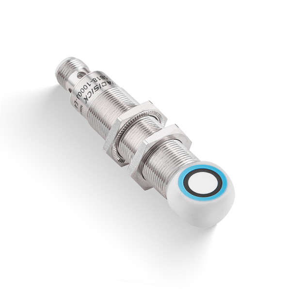
Detection range: 50-500 mm
Material: copper nickel plating, plastic fittings
Connection type: 5-pin M12 connector
Output method: analog voltage + analog current

Detection range: 5000 mm, 15000 mm
Material: Nickel-copper alloy
Connection type: 3pin/4pin with 2M cable

Beam spacing: 2.5mm
Number of optical axes: 32
Protection height: 77.5mm
Similar Posts You May Be Interested in