How to Wire a Safety Light Curtain? (NPN/PNP Wiring Diagrams + Common Issues)
- Share
- publisher
- Zoe
- Issue Time
- Oct 8,2025
Summary
Incorrect wiring of a safety light curtain can not only cause it to malfunction but also create serious safety risks. This article, combined with detailed wiring diagrams, explains the wiring methods for the emitter and receiver, the differences between NPN and PNP output logic, normally open and normally closed circuits, common wiring issues, and practical application cases — helping you gain a comprehensive understanding of safety light curtain wiring.
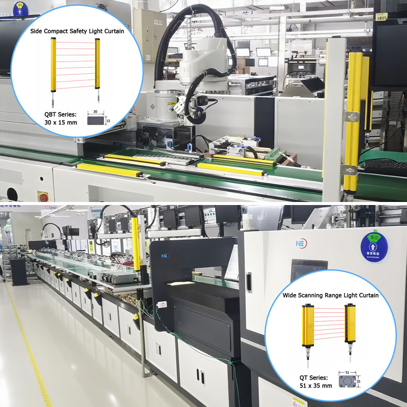
Structure and Function of Safety Light Curtains
A safety light curtain consists of a transmitter and a receiver. The transmitter emits infrared beams, while the receiver detects them to create an invisible safety barrier. When any object interrupts the beam, the light curtain sends a stop signal to prevent potential hazards. It is commonly used in applications such as presses, bending machines, automated lines, and robotic work cells.
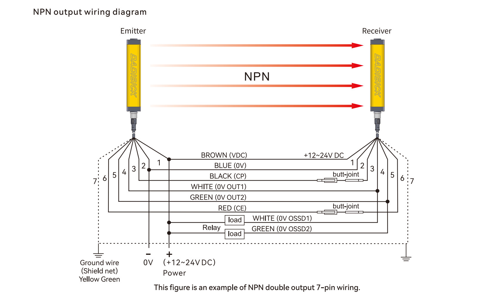
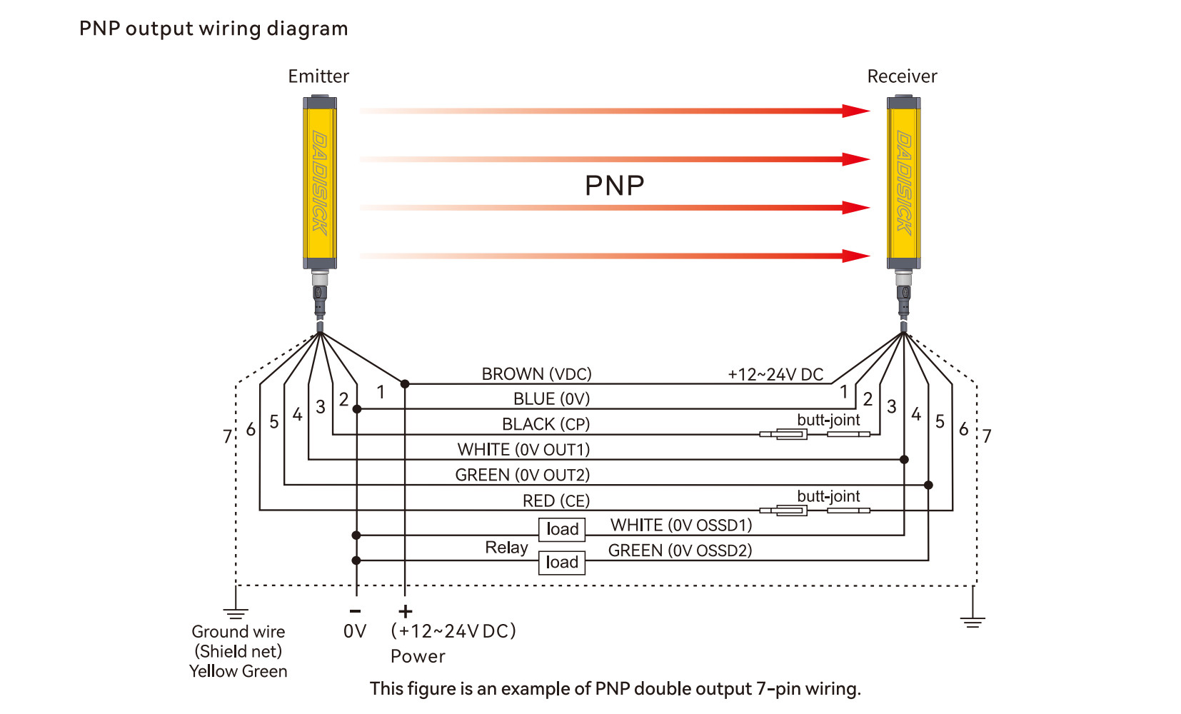
NPN and PNP Output Logic in Safety Light Curtains
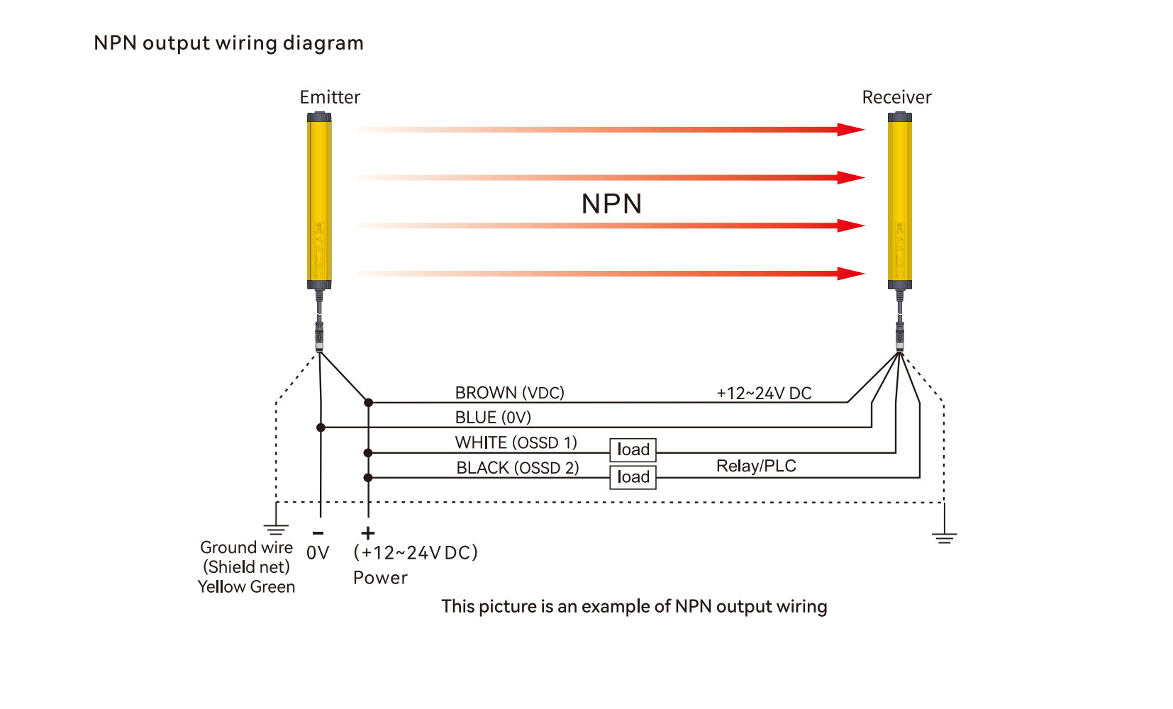
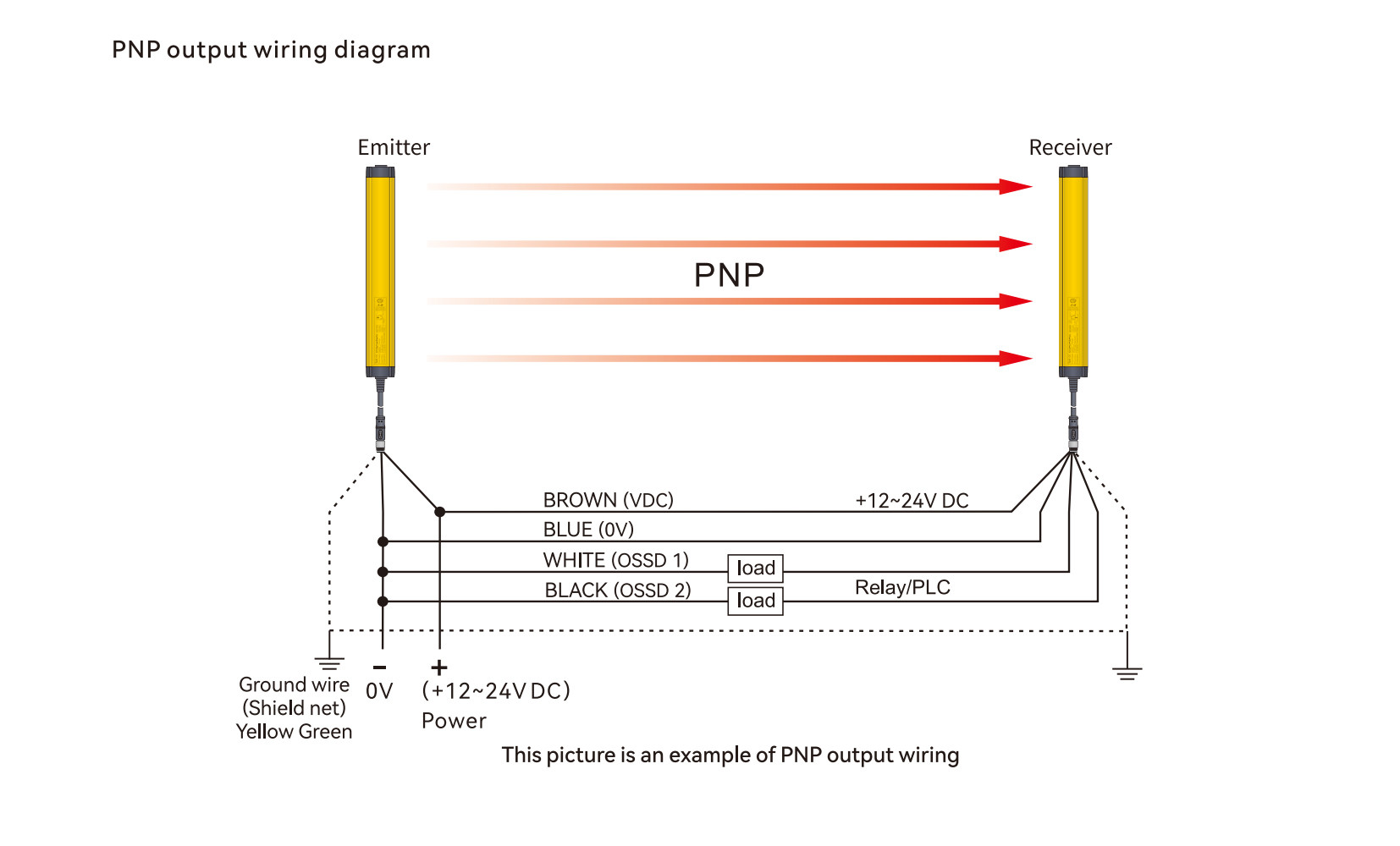
The light curtain OSSD output is available in two configurations — NPN and PNP. Choosing the correct type is critical for compatibility with PLCs or safety relays.
Your safety light curtain output must match the input type of the downstream control device. If you’re uncertain, it’s generally safer to choose PNP output, as most modern safety PLCs and relays support PNP (sourcing) inputs.
| Output Type | State | Output Voltage | PLC Signal |
| NPN NO | Not triggered | Floating ≈ 24V | HIGH |
| Triggered | 0V | LOW | |
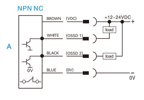
| NPN NC | Not triggered | 0V | LOW |
Triggered | Floating ≈ 24V | HIGH | |
PNP NO | Not triggered | 0V | LOW |
Triggered | +24V | HIGH | |
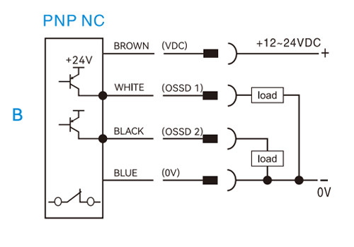
PNP NC | Not triggered | +24V | HIGH |
Triggered | 0V | LOW |
Difference Between Normally Open (NO) and Normally Closed (NC) Outputs
The safety light curtain output signal can be either normally open (NO) or normally closed (NC):
▪️NO (Normally Open): No output signal in normal conditions; signal activates when the beam is blocked.
▪️NC (Normally Closed): Signal present in normal conditions; signal disappears when the beam is interrupted.
In industrial safety systems, NC outputs are often preferred because they can still indicate a “fault” (danger) condition in the event of wire disconnection or device failure, providing higher safety reliability.
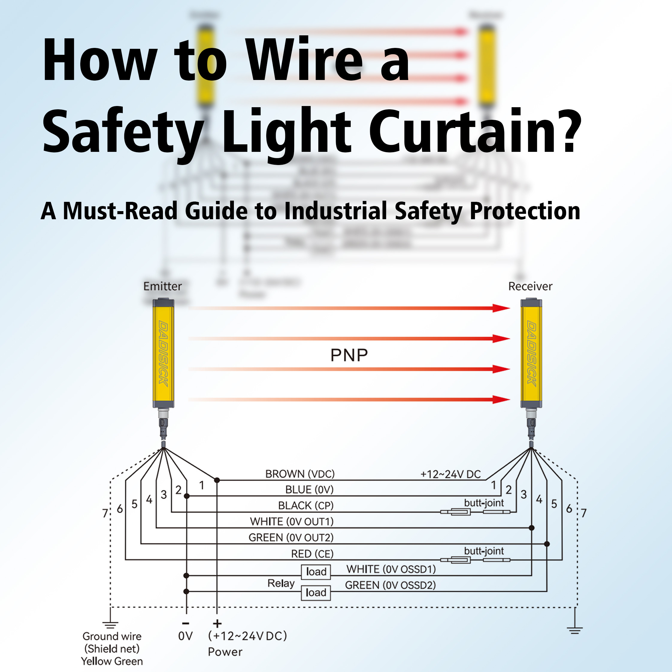
Safety Light Curtain Wiring Diagram Explanation
In a safety curtain sensor connection, the transmitter requires only a power supply, while the receiver needs both power and output signal wiring. The following examples illustrate typical light curtain wiring diagrams.
Example 1: Emitter and Receiver with 7-pin Connectors
Emitter (7-pin)
1. Brown — +24 V DC
2. Blue — 0 V
3. Black — CP
4. White — NC
5. Green — NC
6. Red — CE
7. Yellow — GND
2. Blue — 0 V
3. Black — CP
4. White — NC
5. Green — NC
6. Red — CE
7. Yellow — GND
Receiver (7-pin)
1. Brown — +24 V DC
2. Blue — 0 V
3. Black — CP
4. White — OSSD1
5. Green — OSSD2
6. Red — CE
7. Yellow — GND
2. Blue — 0 V
3. Black — CP
4. White — OSSD1
5. Green — OSSD2
6. Red — CE
7. Yellow — GND
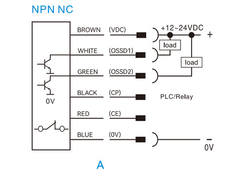
NPN normally closed (NC)
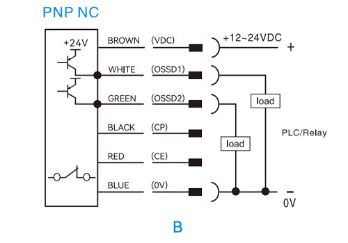
PNP normally closed (NC)
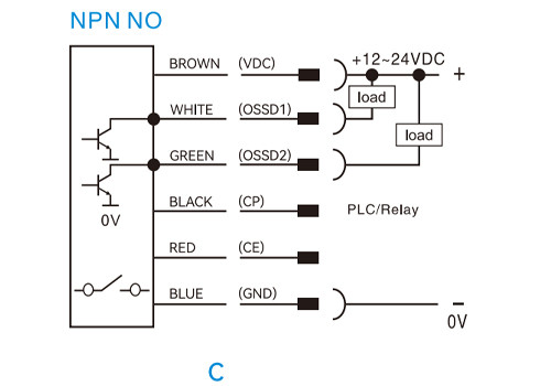
NPN normally open (NO)
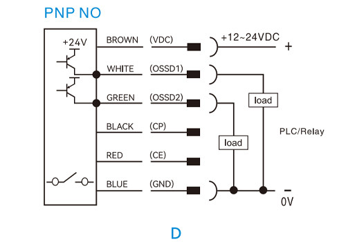
PNP normally open (NO)
Example 2: Emitter with 3-pin, Receiver with 5-pin
Emitter (3-pin)
1. Brown — +24 V DC
2. Blue — 0 V
3. Yellow — GND
2. Blue — 0 V
3. Yellow — GND
Receiver (5-pin)
1. Brown — +24 V DC
2. Blue — 0 V
3. White — OSSD1
4. Black — OSSD2
5. Yellow — GND
2. Blue — 0 V
3. White — OSSD1
4. Black — OSSD2
5. Yellow — GND
NPN normally closed (NC)
PNP normally closed (NC)
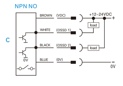
NPN normally open (NO)
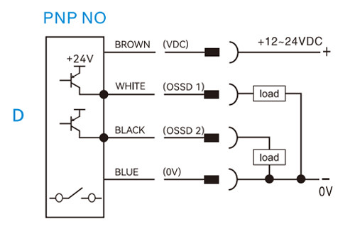
PNP normally open (NO)
💡 Tip: Always refer to the manufacturer’s wiring diagram or user manual, as pin assignments may vary among different brands.
Safety Light Curtain Wiring Precautions
1. Use only DC 24V power — never connect AC power.
2. Ensure correct polarity to avoid circuit damage.
3. Choose either NPN or PNP, never both.
4. Keep signal cables away from high-voltage lines; use shielded cables if necessary.
5. Ensure reliable grounding to enhance anti-interference performance.
6. Confirm PLC input type (sinking or sourcing) before wiring.
7. After wiring, perform a practical blocking test to verify that the logic and outputs match the expected behavior.
Safety Light Curtain Wiring FAQ
Q1: Why doesn’t the safety light curtain power on?
Possible causes include insufficient supply voltage, reversed polarity, or loose connections.
Q2: Why is the output signal always 0V?
Check whether the correct NPN/PNP type is selected and verify compatibility with the PLC input.
Q3: Can NPN and PNP be used simultaneously?
No. Only one output type should be used; connecting both may damage the PLC input circuit.
Q4: Why is the output logic opposite of what I expected?
The safety curtain may use default NC logic. Refer to the product manual to adjust configuration if needed.
Safety Light Curtain Application Examples

Press Machine Guarding
Automatically stops the machine when an operator’s hand enters the hazardous zone.

Bending Machine Protection
Installed near the lower die to prevent accidental contact.

Automated Production Line
Protects entry points of packaging or inspection lines to prevent unauthorized access.

Robotic Work Cell
Installed around robot areas to replace traditional fences and enable flexible human-robot collaboration.
Related Safety Devices

Beam spacing: 30mm
Number of optical axes: 42
Protection height: 1230mm
Safety light curtain outputs (OSSD)2 PNP

Beam spacing: 80mm
Number of optical axes: 10
Protection height: 720mm
Safety Curtain outputs (OSSD):2 PNP

Economical safety relay, dual-channel safety monitoring circuit design, suitable for high-demand fields such as mechanical protection, automated production lines and robot systems.
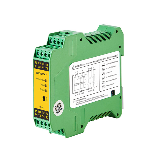
Multifunctional safety relay, providing automatic/manual reset configuration and multifunctional configuration DIP switch, used for industrial field monitoring of various signals with high safety requirements.
Similar Posts You May Be Interested in