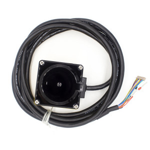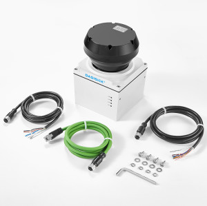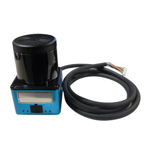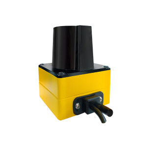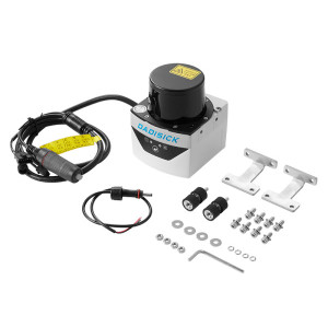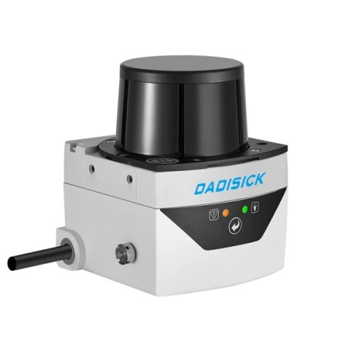
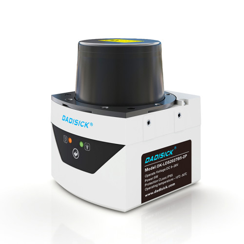
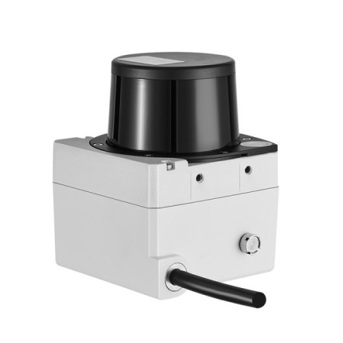
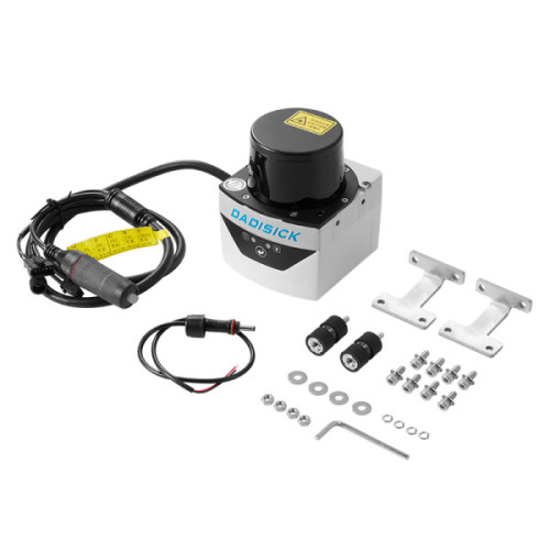
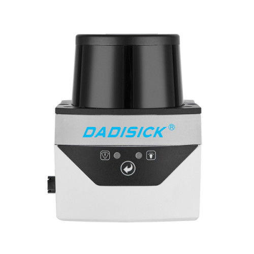
20-meter obstacle avoidance navigation | LiDAR scanner | Redundant output
- Model
- DK-LDS2027B5-2P Series
Item specifics
- Sensing range:
- 0.1 m ~ 20 m
- Scanning frequency:
- 25 Hz
- Scanning angle range:
- 300°
- Angular resolution
- 0.5°
- Light source:
- Infrared laser (905 nm)
- Laser safety level:
- Class 1 (GB7247.1-2012, Eye-safe IEC)
Review
Description
|
Laser Scanning Radar Basic Information
|
||
|
Product number
|
Two-dimensional tof obstacle avoidance laser radar scanner |
|
|
Model
|
DK-LDS2027B5-2P |
|
Output | I/O output & Ethernet output | |
|
Features
|
||
|
Light source
|
Infrared laser (905 nm) |
|
Laser safety level | Class I (GB 7247.1-2012, Eye safe IEC) | |
Laser spotlight diameter | 8 mm | |
Laser spotlight scan angle | 12.5 mrad | |
|
Scanning angle range
|
300° |
|
|
Scanning frequency
|
25 Hz |
|
|
Scanning Angular Resolution
|
0.5° |
|
Sensing range | 0.1 m ~ 20 m | |
10% reflectivity range | 15 m | |
Self-learning function | Automatic environment scanning, generating area | |
Outdoor performance | Anti-dusty, Anti-sunlight | |
Rain, fog and smoke penetration | Supported | |
Technical Performance | ||
Measurement error ● System error {typical} ● Statistcal error {1 σ} | 1 cm | |
Built-in application | ● Regional monitoring ● Monitoring mode: Point number monitoring / target width monitoring / contour monitoring ● Monitor signal level: Attention / warning / alarm ● Number of regional groups: 16 groups, support self-learning background exclusion ● Concurrent work area group number: 16 (max) ● Guide the network camera to monitor the target video positioning and tracking | |
Self-test equipment | ● Contents: Transparent cover dirt / block / high temperature / low temperature ● Output mode: indicator + TCP packets | |
Device Interface | ||
Ethernet | Rate: 10/100 Mbps Network protocol: TCP/IP Function: Device configuration / measurement data output / monitor signal output | |
I/O Input | Input port: 4 Type: Level input High level range: DC 10 V - 30 V Low level range: DC 0 V - 1.2 V Preset functions: Monitor area group selection (0 × 0 ~ 0 × F) Forced cancellation / forced activation of regional monitoring signal, effective level: high level Power saving and life extension control, effective level: high level | |
I/O Output | Input port: 4 Type: PNP switch output Maximum switch voltage: DC30V Power-on state: OFF Preset function:
Device ready / area monitoring signal output, effective state: configurable | |
Indicator light | Quantity: 2 Definition: HTR (Run status indication: detection signal / self-learning / ready to restart) ERR (Device alarm: Transparent cover dirt / block, high and low temperature) | |
Front panel button | Quantity: 1 Definition: Shielded monitor signal output / start background self-learning / restart device | |
|
Mechanical/electronic paramete
|
||
|
Operating voltage
|
DC 10 V – 30 V |
|
|
Power dissipation
|
3.4 W (measuring), 7.6 W@DC 12 V / 6 W@DC 24 V (heating) |
|
|
Degree of protection (IP)
|
IP67 (GB 4208-2008) |
|
Insulation resistance | 1 MΩ (GB 16796 - 2009.5.4.4) | |
Electric strength | 0.5 KV (GB 16796 - 2009.5.4.3) | |
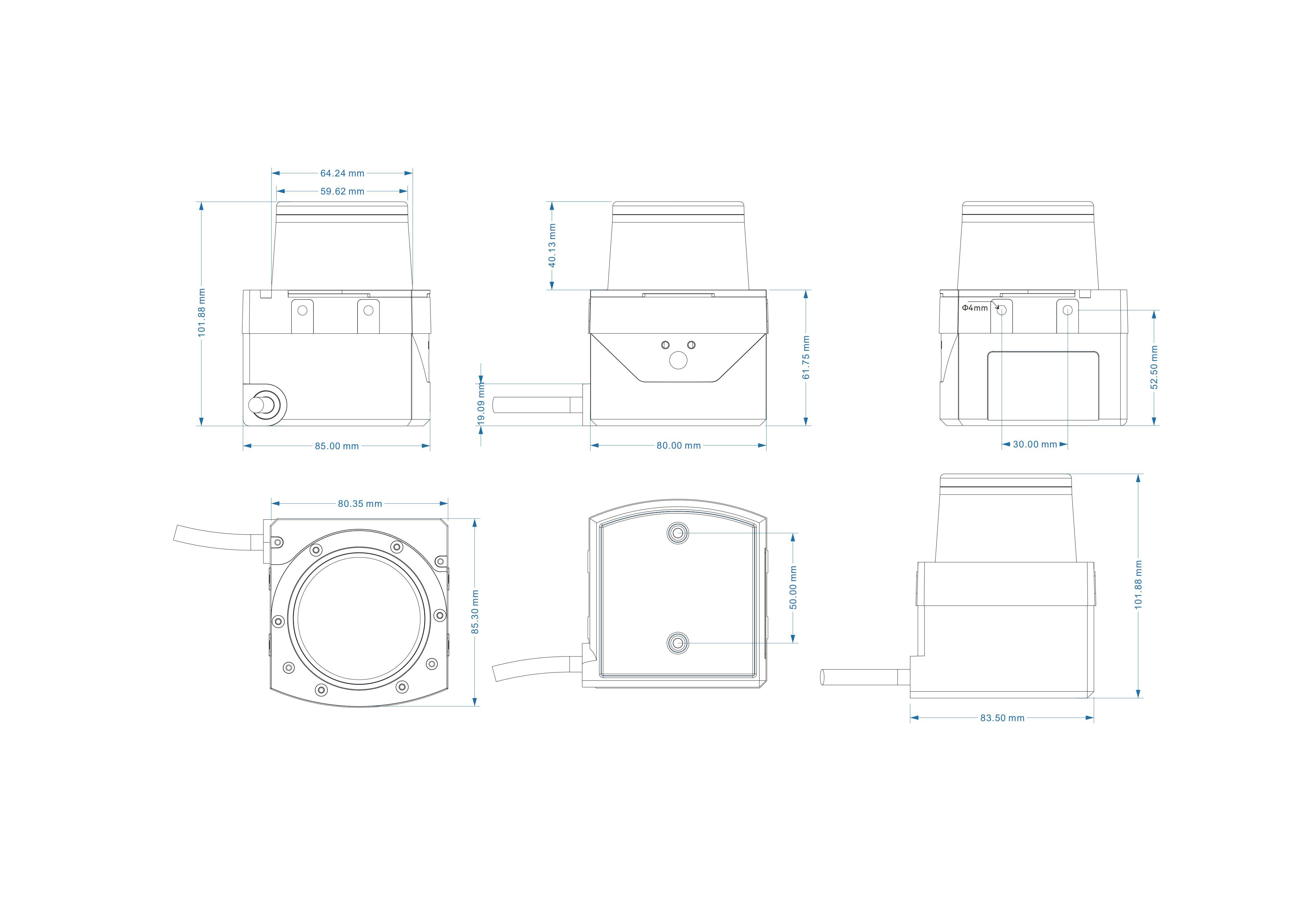
Dimension (L ╳ W ╳ H) | 80 ╳ 85 ╳ 102 (mm) | |
Interface cable lengt | 1 Meter | |
Weight | 0.6 kg | |
DIMENSION
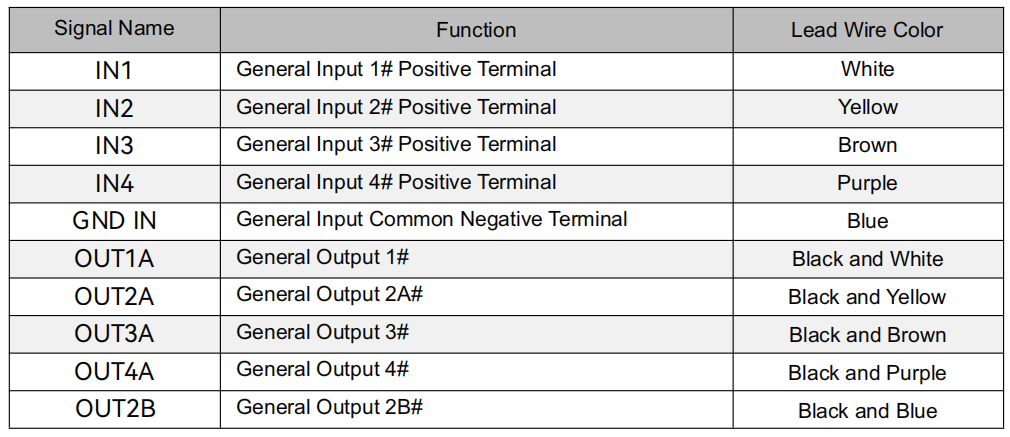
I/O Interface Signal Definitions
PNP Wiring Diagram
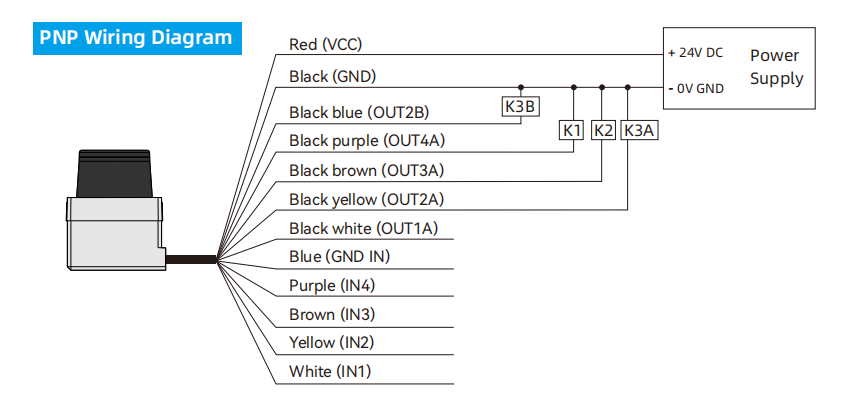
illustrate:
The input signals at the general-purpose input positive terminals "IN1…IN4" are level inputs (vs. the general-purpose input common negative terminal "GND IN"), with logic states of "high" and "low".
The general-purpose output terminals "OUT1…4A, OUT2B" are PNP switch outputs (vs. polarity is "power supply positive terminal"), with logic states of "on" and "off". OUT2A and OUT2B are redundant outputs with fully synchronized physical signals.
The device power supply negative terminal GND must be used as the power supply negative terminal for the external circuitry of the I/O terminals.
DOWNLOADS
3D