How To Set Up An Ultrasonic Sensor With Switch Output? Entry-Level Wiring And Testing Methods
- Share
- publisher
- Zoe
- Issue Time
- May 23,2025
Summary
This article provides a practical guide to wiring and testing an ultrasonic sensor with switch output. Using the CSB30 Series as an example, we demonstrate how to configure detection distances within the sensor’s range using basic setup methods.
Why Choose an Ultrasonic Sensor with Switch Output?
Switch output is the simplest and most widely used signal type for ultrasonic sensors, commonly available in PNP or NPN configurations. It features only two states: ON (high or low level, depending on logic) and OFF. This makes it ideal for presence/absence detection and for determining whether an object has entered or exited a predefined detection zone.
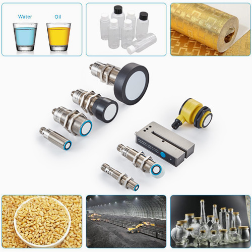
Applications typically include:
Detecting the presence of items on a production line
Monitoring whether liquid levels reach a specific point
Counting objects passing a defined position
Basic object positioning within a specified area
Key advantages of switch output:
Simplicity: Wiring is straightforward. The sensor output can be connected directly to PLCs, relays, or digital input pins of microcontrollers.
Speed: Suitable for scenarios requiring fast, binary feedback without the need for complex data processing.
Versatility: Ideal for threshold-based control tasks, such as opening automatic doors, triggering collision avoidance systems, or activating emergency stop functions.
However, it is important to note that this output type does not provide actual distance values. It is most suitable for applications where precise distance measurement is not required.

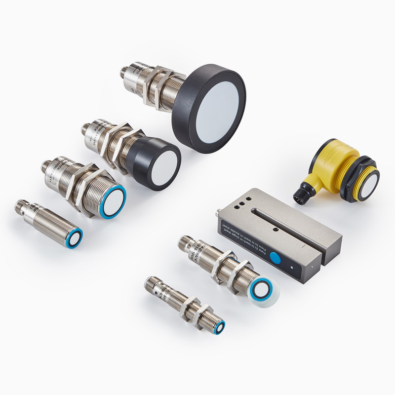
Ultrasonic Sensor with Switch Output: An Overview
An ultrasonic sensor with switch output operates based on the principle of time-of-flight distance measurement. The sensor compares the measured distance to a user-defined threshold and outputs a binary (digital) signal accordingly. When the detected object is within the threshold range, the sensor switches its output state—enabling use in alarms, control logic, or device activation.
Working Principle: Distance Measurement and Threshold Switching
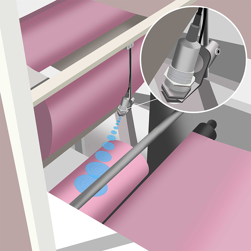
1. Ultrasonic Transmission and Echo Detection
The sensor emits high-frequency ultrasonic pulses (typically 20–40 kHz, inaudible to humans) through its transmitter. These waves travel through air, reflect off nearby objects, and are received by the sensor’s built-in receiver.
By measuring the time interval (Δt) between pulse emission and echo reception, the sensor calculates the object’s distance using the formula:
d = v × Δt / 2,
where v is the speed of sound in air (~340 m/s, with temperature compensation applied).
2. Threshold Comparison and Digital Output
The user can configure a switching threshold via potentiometer, button, or communication interface.
A microcontroller (MCU) inside the sensor continuously compares the real-time measured distance to the threshold.
If distance ≤ threshold, the output switches to high or low level (depending on logic) – indicating object presence.
If distance > threshold, the output reverts – indicating no object detected.
3. Output Signal Format
The output is a standard digital GPIO signal, suitable for:
Direct control of relays, indicators, buzzers, etc.
Input to PLCs, microcontrollers, or other digital control systems.
Setting Procedure for Ultrasonic Sensors with Switch Output
Ultrasonic Sensor Connection
1. Mount the Sensor and Connect the Cable
Begin by securely mounting the ultrasonic sensor at the desired installation location. Connect the sensor to the system using the appropriate cable, ensuring a firm and reliable connection at the connector interface.
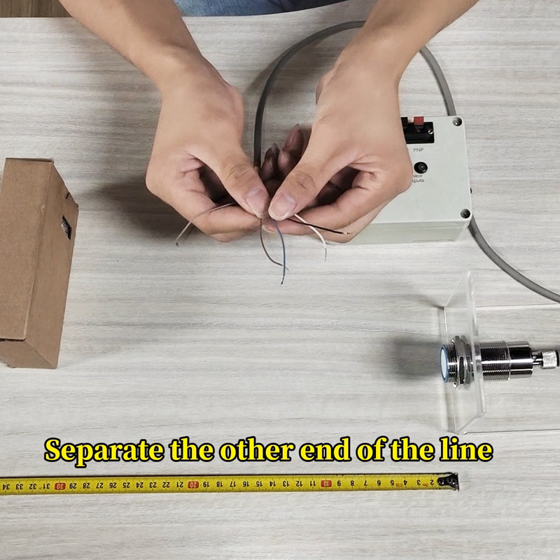
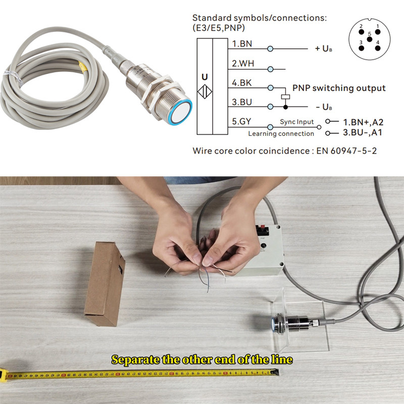
2. Wiring the 5-Core Cable
The five wires of the sensor should be connected according to the standard color codes:
Brown: Connect to the positive power supply (+V)
Blue: Connect to the negative power supply (0V)
Black: Switching output signal (Switching Output)
Grey: Teach-in wire for setting the detection points
White: Reserved for future use or optional functions (refer to the product manual for specific instructions)
Ultrasonic Distance Measurement
3. Teach-in Procedure for Switching Point Configuration (Window Mode)
The sensor allows the configuration of two switching points within the detection range to create a defined sensing window:
First Detection Point (A1):
Place the target object at position A1, which represents the starting point of the desired detection range.
Temporarily connect the grey Teach-in wire to 0V (negative pole). Wait until the sensor’s indicator LED (typically green) blinks three times, then disconnect the wire. This confirms that the first switching point has been set.
Second Detection Point (A2):
Move the object to position A2, representing the end point of the detection window.
Temporarily connect the grey wire to +V (positive pole). Once the LED flashes three times again, disconnect the wire.
At this stage, the sensor has successfully completed the dual-point configuration for window mode, and the system is ready for operation.
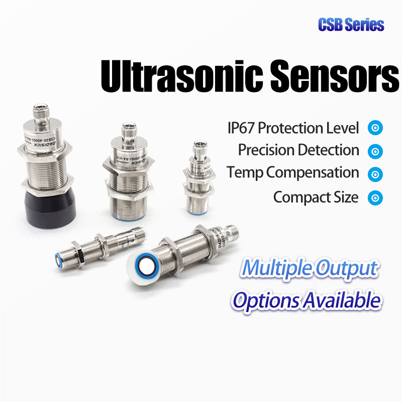
Recommended Ultrasonic Sensors
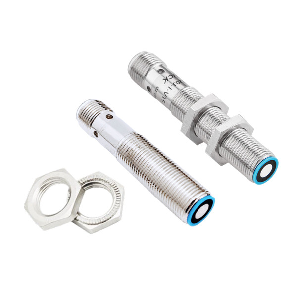
- Model: DK-CSB30-2000-J60-E3-V15
- Detection range: 100-2000 mm
- Detection range: 100-2000 mm
- Blind zone: 0-100 mm
- Resolution: 0.17 mm
- Resolution: 0.17 mm
- Repeatability ±0.15% of full-scale value
- Absolute accuracy: ±1% (built-in temperature drift compensation)
- Response time: 82 ms
- Response time: 82 ms
- Switching hysteresis: ±2 mm
- Switching frequency: 10 Hz
- Input type: With synchronization and learning function
- Output type: E3/E5: 1 PNP switch output, NO/NC
- Weight: 105 g
- Operating voltage: 10-30 V DC, reverse polarity protection
- Operating voltage: 10-30 V DC, reverse polarity protection
- Overpower protection: 200 mA , red light and green light flashing at the same time
- Load impedance: I / 0-300 Ohm , U / > 1k Ohm
- No-load current: ≤ 30 mA
- Material: Copper nickel plating , plastic fittings , glass filled epoxy resin
- Connection type: 5-pin M12 connector
- Protection Class: IP 67
- Ambient temperature: -25°C~+70°C (248~343K)
Related Sensors
Detection range: 100-2000 mm
Material: copper nickel plating, plastic fittings
Connection type: 5-pin M12 connector
Output method: 1 PNP switch output, NO/NC
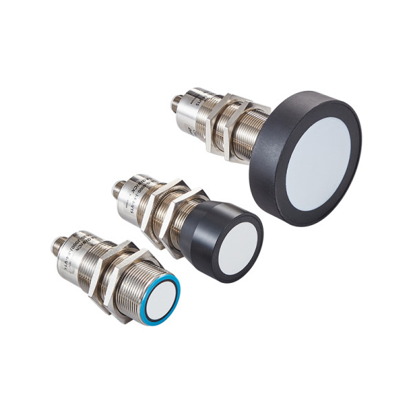
Detection range: 30-300 mm, 50-500 mm, 60-1000 mm
Material: copper nickel plating, plastic fittings
Connection type: 5-pin M12 connector
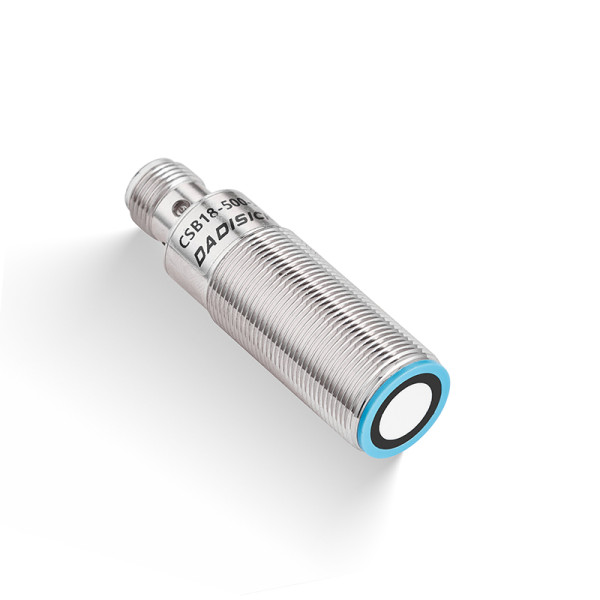
Detection range: 20-120mm
Material: copper nickel plating
Connection type: 4-pin M12 connector
Output method: 1 NPN switch output, NO/NC
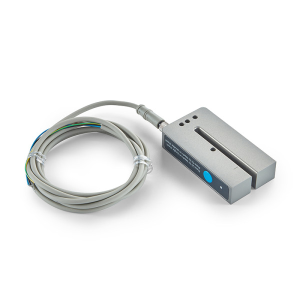
Groove depth: 68 mm
Slot width: 5 mm
Material: metal, aluminum
Connection type: 4-pin M8 connector