Safety Light Curtain Installation: An In-Depth Practical Guide for Engineers
- Share
- Issue Time
- Dec 11,2025
Summary
Detailed installation guide for safety light curtains: determine PLr, calculate safety distance, align and wire OSSD outputs, validate response time, and maintain reliability.

Safety light curtains are a cornerstone of machine safeguarding in modern industrial automation. When properly specified, installed, and maintained, they provide non-contact protection for operators working near hazardous machinery—presses, robots, conveyors, packaging lines, and more. Yet poor installation or misunderstanding of safety principles leads to failures in the field far more often than hardware defects. This article provides a detailed, engineering-level walkthrough—from planning and calculations to wiring, validation, and maintenance—so your installations meet performance expectations and regulatory requirements.
Start with a Risk Assessment and Define PLr
Why is a risk assessment the first step
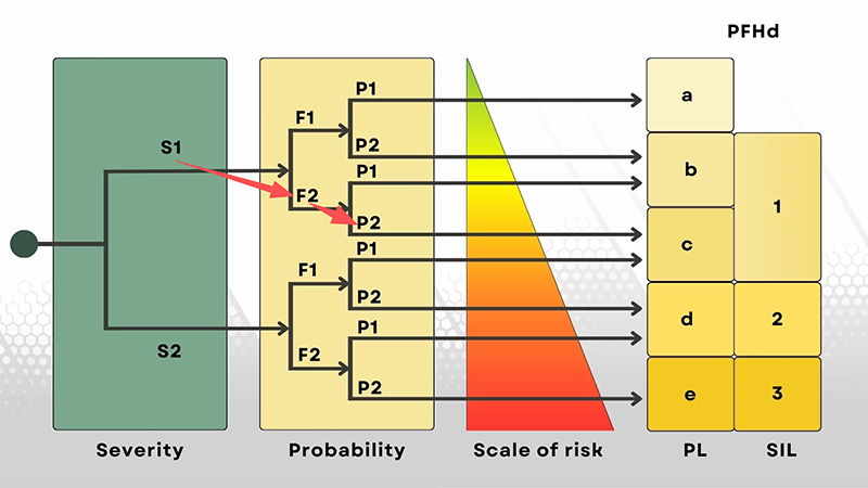
Before selecting any safety device, perform a formal risk assessment. The outcome determines the required Performance Level (PLr) for each safety function (e.g., presence detection, guard locking, emergency stop). PLr is not an abstract label—it dictates architecture, diagnostics, and component choices. The assessment evaluates: severity of potential injury (S), frequency and duration of exposure (F), and possibility of avoiding the hazard (P). These three inputs map to PLr per ISO 13849-1.
Practical assessment process and examples
A practical process: identify tasks (operator loading, tool change), list hazardous motions (press closing, robot swing), evaluate S/F/P for each task, and use the PL risk graph to find PLr. For example, loading a press by hand where severe injury is possible (S = high), exposure is frequent (F = high), and avoidance is difficult (P = low) → PLr could be d or e. That immediately informs you that the safeguarding system must use redundant architecture, high MTTFd components, and good diagnostic coverage. See Dadisick's PL guidance for deeper context: Performance Levels (PL) Guide.
Select the Right Light Curtain Type and Resolution
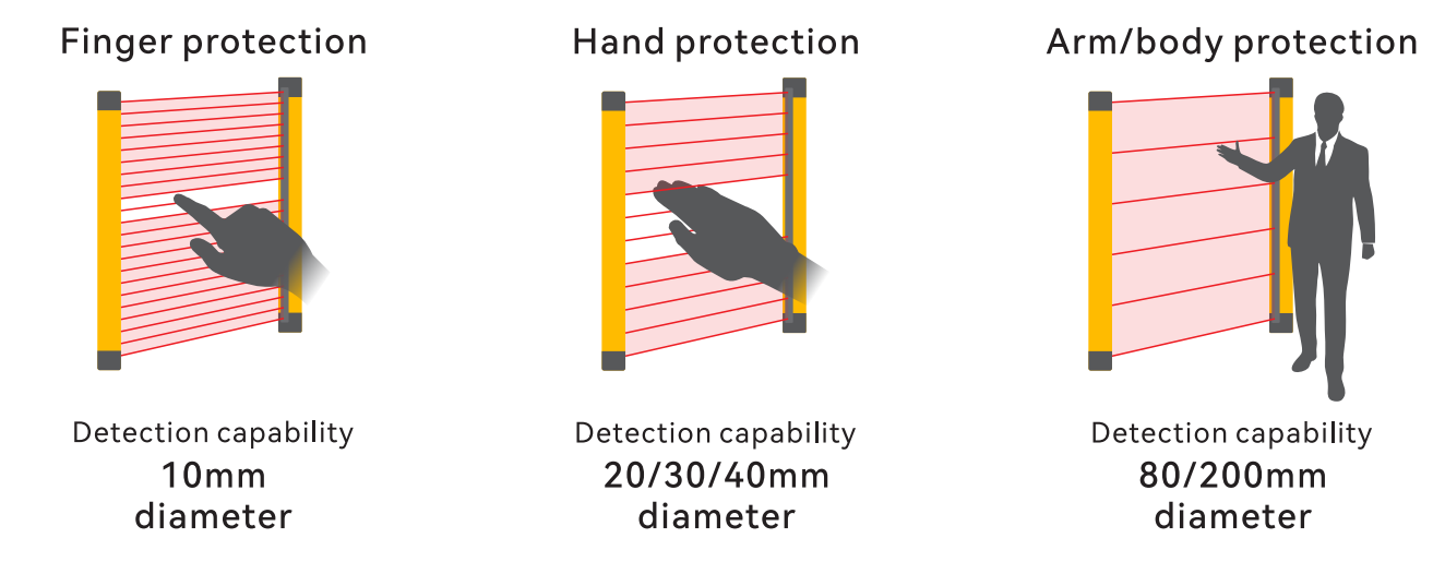
Resolution (detection capability) — how small is too small?
Resolution indicates the smallest object the curtain will reliably detect. Typical values: 14 mm (finger), 20–30 mm (hand), 40 mm+ (limb/body). Choosing a resolution depends on the task: if the operator's hand approaches a point of operation containing blades or dies, 14 mm is often required. But resolution alone is insufficient—consider also mounting geometry and approach direction (vertical/horizontal).
Engineering tip: calculate potential intrusion geometry—if a gloved hand or tool will be used, add a margin to the resolution selection. Also, check the curtain's certified resolution under the actual mounting distance, as some devices change effective resolution with distance.
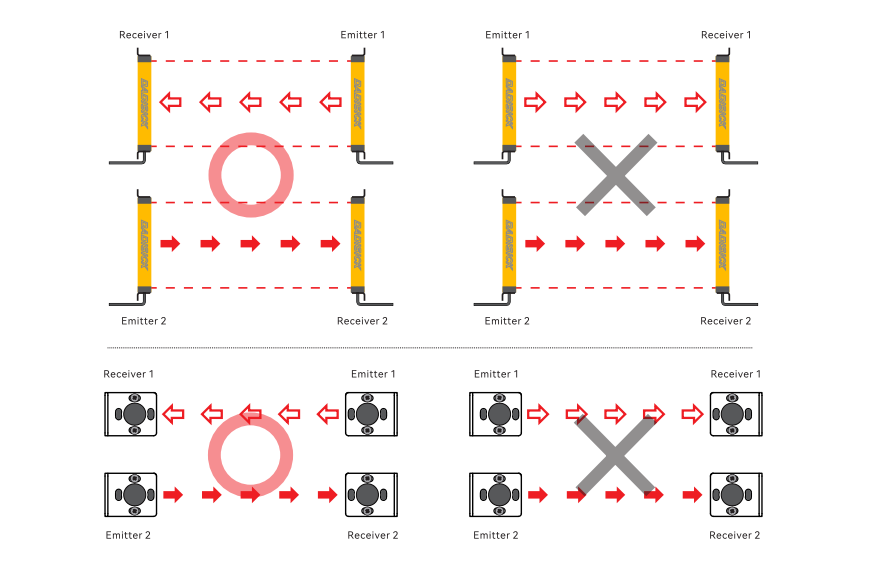
Light curtain types — Type 2 vs Type 4 and functional implications
IEC/EN classifies light curtains by performance type (Type 2, Type 4). Type 4 offers higher diagnostic and fault-tolerant behavior, intended for higher PL systems (PL d/e). For critical machines, specify Type 4 devices with clear OSSD outputs and MTTFd data.


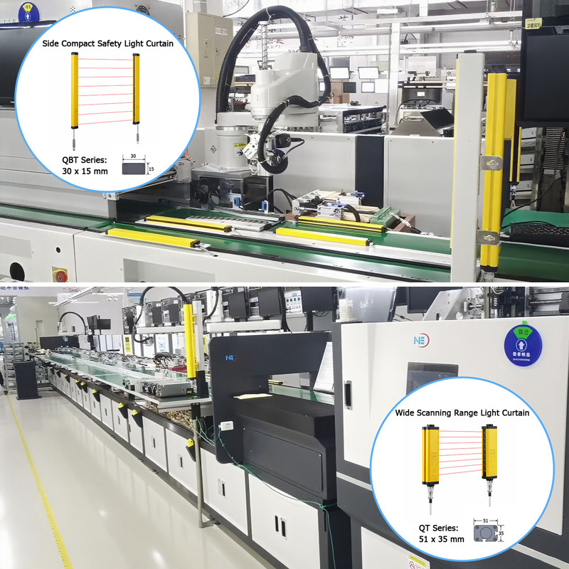
Long-range and wide-area considerations (DK-QT series example)
Large machinery or wide infeed areas may require long-range or wide-scanning light curtains. DADISICK's DK-QT Series is designed for broad scanning ranges and consistent detection across extended widths, making it suitable for conveyor guarding or multi-operator zones. Ensure the device's scanning geometry matches the application and verify detection performance across the entire protected field.
Calculate and Verify Minimum Safety Distance (ISO 13855)
The safety distance concept and formula
The generic formula: S = K × T + C
where:
· S = required safety distance (mm)
· K = approach speed constant (e.g., 1,600 mm/s for hand = 1.6 m/s in many regions; use local standard)
· T = total system stopping time (light curtain response + safety relay/PLC + machine stopping time)
· C = additional constant related to protective device resolution and intrusion method (per ISO 13855)
Measuring and summing T (total stopping time) accurately
T is the sum of several measurable components:
· Device response time (td_device) — the time between beam interruption and OSSD change (specified by device datasheet).
· Safety monitoring time (td_monitor) — time for the safety relay/PLC to process input and command outputs.
· Machine stopping time (td_machine) — time from stop command to hazardous motion cessation. This must be measured on the actual machine, not estimated.
Engineering procedure: measure td_machine with a controlled test (simulate intrusion and time to full stop), add device and monitoring times (from datasheets and relay specs), then compute S. Always add conservative margins for aging and variable operating conditions.
Documenting the calculation for compliance
Record the formula, measured times, assumptions (approach speed used), and safety distance decisions in the installation dossier. Auditors expect precise calculations and traceable measurements.
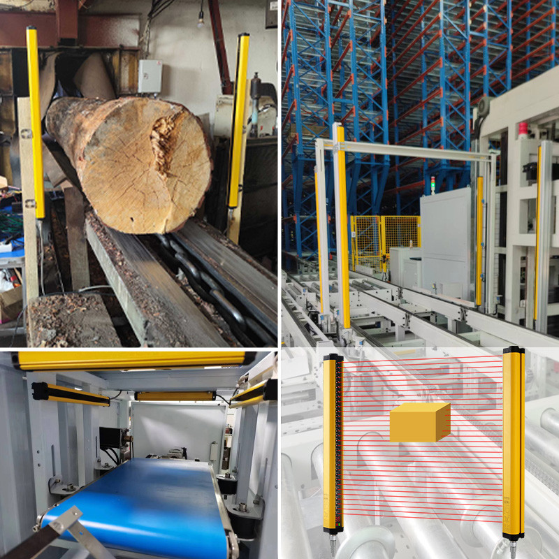
Mounting, Alignment, and Mechanical Considerations
Rigid mounting and vibration control
Even small angular shifts cause beam misalignment. Mount transmitters and receivers to rigid structures; avoid flexible frames. If unavoidable, use vibration dampers or additional bracing. Torque mounting hardware to specified values and use thread-lock compounds in high-vibration environments.
Alignment techniques and tools
Use built-in LEDs, alignment lasers, or portable detectors to align beams precisely. After initial alignment, lock adjustment points, and running a cyclic test (operating the machine at speed while checking for spurious faults). Re-verify alignment after the first week of operation.
Avoiding reflections and optical noise
Polished surfaces, glass, and thin plastic films can reflect infrared beams and create ghost signals or masking. Keep a clearance (typically 50–100 mm depending on geometry) from reflective panels, or fit anti-reflection covers. For welding environments, use shields and synchronize with weld cycles or choose filters tolerant to arc light.
Wiring, OSSD Outputs, and Safety Integration
Using proper safety relays and controllers
Light curtains produce safety outputs (often OSSD). These outputs must connect to certified safety relays or safety PLCs that provide dual-channel monitoring, cross-circuit detection, and safe restart logic. DADISICK's safety relays are designed for such integration and include required diagnostic features.
Wiring best practices and EMC considerations
· Use separate conduits for power and signal cables.
· Ground shields correctly at one end to avoid ground loops.
· Maintain recommended wire lengths and use recommended cable types to preserve timing and diagnostics.
· Wherever possible, route safety wiring away from drives, inverters, and heavy machinery to reduce EMI risk.
Cross-circuit protection and redundancy checks
Redundancy only provides safety if channels are independent. Avoid common wiring segments between channels; each channel should be physically separated where possible. Check for common cause failure exposures (e.g., a clamp crushing both channels).
Functional Testing, Validation, and Commissioning
Beam interruption and approach tests
Use calibrated test rods or standardized test specimens to block beams at different heights and positions. Test both single and multi-beam interruptions. Validate detection under dynamic conditions (moving conveyors, part ingress).
Response time and safety chain verification
Trigger a beam interruption and measure elapsed time to machine stop (preferably with an oscilloscope or test logger). Compare with the calculated T used in the safety distance. Reconcile any discrepancies—do not accept measured times longer than calculated.
Documented verification and sign-off
Create a commissioning checklist covering alignment, safety distance verification, wiring inspection, E-stop function, controlled restarts, and training. Have responsible engineers sign off; retain records for compliance and insurance.
Commissioning Scenarios and Edge Cases
Muting and blanking—use with caution
Muting (temporary suppression of material flow) and blanking (permanent suppression of certain beams for part passage) are powerful but risky. Implement muting only with clear logic (sensors that detect material flow) and safeguard against operator-induced bypass. Verify muting logic under fault conditions.
Cascading and multi-sided protection
For large or multi-access areas, cascading multiple curtains is common. Use curtains that support auto-cascade or synchronized beams to prevent cross-talk. Ensure each cascade link includes safe verification and does not introduce single points of failure.
Tooling changes and re-validation
After tooling changes (dies, fixtures), revalidate protection height, safety distance, and any blanking/muting logic. Even small tooling differences can alter intrusion geometry and invalidate prior calculations.
Maintenance, Periodic Testing, and Long-Term Reliability
Routine inspection schedule
Define inspection intervals based on duty cycles and environment (weekly for dirty/abrasive environments, monthly in cleaner settings). Inspections should include visual checks, alignment verification, and beam status LED readings.
Predictive diagnostics and using device diagnostics
Modern curtains supply diagnostic outputs (alignment error, beam block fault, internal fault). Integrate diagnostics into maintenance dashboards (via IO-Link or Ethernet) to predict failures before they become critical.
Replacement planning and lifecycle management
Track mean time to dangerous failure (MTTFd) data and plan component replacement/recalibration before diagnostic thresholds degrade. Maintain spares for critical models to reduce downtime.
Common Mistakes and How to Avoid Them
Mistake — Relying on assumed stopping time
Measure machine stopping time rather than relying on catalog numbers. Real machines with worn brakes or variable loads can have much longer stopping times.
Mistake — Using the wrong approach speed constant (K)
Use a conservative approach if operator behavior is uncertain. If operators frequently rush or use tools, use higher K values to ensure the safety distance is sufficient.
Mistake — Treating muting as a convenience rather than a controlled function
Muting must be rigorously validated; do not use muting to hide design deficiencies.
Conclusion — Build Safety into the Installation Process
A safety light curtain is not a plug-and-play component; it's a safety system element. Quality installations derive from careful risk assessment (defining PLr), measured timing and distance calculations, correct device selection (resolution, type), proper mounting and wiring, and documented validation and maintenance. When combined with certified safety relays and controllers, and when engineers follow structured commissioning and change-control processes, light curtains reliably protect operators and support productive automation.
For integrated safety systems—light curtains, relays, and performance guidance, etc.—DADISICK provides a full portfolio of compliant solutions to help you design, install, and maintain safe machines.
Related Safety Devices

Beam spacing:40mm
Number of optical axes:20
Protection height:760mm
Safety sensors for machines output (OSSD):2 PNP
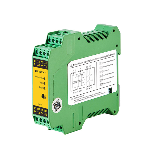
Multifunctional safety relay, providing automatic/manual reset configuration and multifunctional configuration DIP switch, used for industrial field monitoring of various signals with high safety requirements.

By converting from the laser into electrical signals. determine various characteristics,distance, displacement, or position.
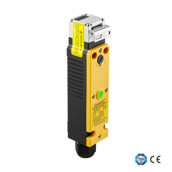
Used for monitoring places such as safety doors and windows.
Similar Posts You May Be Interested in